
All Solutions
Page 775: Assessment
Even if there was a local charge transfer from the comb to the hair (or another way around) the net charge on the comb and our hair is still zero. From this, we can conclude that there is no charge transfer.
Since we are having a net charge on the comb and we start walking, we have a “flow” of the current, because there a movement of excessive charge (sum of the charge on the comb is not zero anymore.
$$begin{align*}
V=IR
end{align*}$$
$$begin{align*}
I=frac{V}{R}=frac{V_0}{R_0}=1;text{A}
end{align*}$$
$$begin{align*}
I_text{A}=frac{2V_0}{4R_0}=frac{1V_0}{2R_0}=frac{1}{2}I=boxed{0.5;text{A}}
end{align*}$$
$$begin{align*}
I_text{B}=frac{4V_0}{4R_0}=frac{V_0}{R_0}=I=boxed{1;text{A}}
end{align*}$$
$$begin{align*}
I_text{C}=frac{4V_0}{2R_0}=frac{2V_0}{R_0}=2I=boxed{2;text{A}}
end{align*}$$
$I_text{B}=1;text{A}$
$I_text{C}=2;text{A}$
Considering this we are having a chain effect (every charge moving due to the field of the neighbor charge) or in other words, commonly called signal, that is really fast and happening instantaneously.
Today this is known only as a convention, as we really know that electrons in the wire are the carriers of the current, so the real direction would be from negative to the positive terminal, which is indeed a direction that would allow electron flow.
$$
I = frac{Delta Q}{Delta t}
$$
Since we know that our charges are electrons and we want to find out how many of them we know that $Delta Q = ne$, so we can write:
$$
I = frac{n e}{Delta t}
$$
Expressing a number of the electrons from this, we have:
$$
n = frac{I Delta t}{e}
$$
Putting in the numbers we have:
$$
n = frac{12 times 10^{-12} mathrm{~A} cdot1 mathrm{s}}{1.6 times 10^{-19 } mathrm{C}}
$$
We have the result of:
$$
boxed{color{#c34632}n = 7.5 times 10^{7}}
$$
n = 7.5 times 10^{7}
$$
$$
I=frac{Delta Q}{Delta t}
$$
Expressing time interval from this, we have:
$$
Delta t = frac{Delta Q}{I}
$$
Putting in the numbers:
$$
Delta t = frac{12 mathrm{C}}{0.15 mathrm{A}}
$$
We have the result of:
$$
boxed{color{#c34632}Delta t = 80 mathrm{~s}}
$$
Delta t = 80 mathrm{~s}
$$
$$
I=frac{Delta Q}{Delta t}
$$
Expressing time interval from this, we have:
$$
Delta t=frac{Delta Q}{I}
$$
Putting in the numbers:
$$
Delta t=frac{0.25 mathrm{C}}{1.1 mathrm{~A}}
$$
We have the result of:
$$
boxed{color{#c34632}Delta t=0.227 mathrm{~s}}
$$
Delta t=0.227 mathrm{~s}
$$
$$
W = Delta Q V
$$
Expressing the voltage difference we have:
$$
V= frac{W}{Delta Q}
$$
Putting in the numbers we have:
$$
V= frac{59 mathrm{J}}{6.6 mathrm{~C}}
$$
We have the result of:
$$
boxed{color{#c34632}V= 8.93 mathrm{~V}}
$$
V= 8.93 mathrm{~V}
$$
$$
W=Delta Q V
$$
Expressing charge from this we have:
$$
Delta Q = frac{W} {V}
$$
We put in the numbers from the problem statement:
$$
Delta Q = frac{41 mathrm{~J}}{12 mathrm{~V}}
$$
It gives the result for charge:
$$
boxed{color{#c34632}Delta Q = 3.42 mathrm{~C}}
$$
Delta Q = 3.42 mathrm{~C}
$$
$$
R=frac{U}{I}
$$
Expressing voltage from this we have:
$$
U = IR
$$
Putting in the numbers from the problem statement, we have:
$$
U = 2.2 mathrm{~A} cdot 140 mathrm{Omega}
$$
and we have the result of:
$$
boxed{color{#c34632}U = 308 mathrm{~V}}
$$
U = 308 mathrm{~V}
$$
$$
R=frac{U}{I}
$$
Expressing the current from this we have:
$$
I= frac{U}{R}
$$
And putting in the numbers from the problem statement:
$$
I= frac{15 mathrm{~V}}{210 Omega}
$$
Give the result of:
$$
boxed{color{#c34632}I= 0.0714 mathrm{~A}}
$$
I= 0.0714 mathrm{~A}
$$
$$
R=frac{U}{I}
$$
Putting in the numbers from the problem statement we have:
$$
R=frac{95 mathrm{~V}}{3.2 mathrm{~A}}
$$
We have the result of:
$$
boxed{color{#c34632}R=29.62 Omega}
$$
R=29.62 Omega
$$
$$
I=frac{Delta Q}{Delta t}
$$
Expressing time interval from this, we have:
$$
Delta t=frac{Delta Q}{I}
$$
Putting in the numbers:
$$
Delta t=frac{1500 mathrm{C}}{5.6 times 10^{-6} mathrm{~A}}
$$
We have the result of for pacemaker lifetime
$$
Delta t=2.68 times 10^8 mathrm{~s}
$$
Delta t=2.68 times 10^8 mathrm{~s}
$$
$$
I=frac{Delta Q}{Delta t}
$$
Putting in the information from the problem statement we have:
$$
I=frac{9.6 mathrm{~C}}{45 mathrm{~s}}
$$
$$
boxed{color{#c34632}I=0.213 mathrm{~A}}
$$
For the $textbf{part b}$ we calculate the work done by the battery:
$$
W= V Delta Q
$$
Putting in the numbers we have:
$$
W= 1.5 mathrm{~V} cdot 9.6 mathrm{~C}
$$
We have the result of:
$$
boxed{color{#c34632}W= 14.4 mathrm{~J}}
$$
(a) I=0.213 mathrm{~A}
$$
$$
(b) W= 14.4 mathrm{~J}
$$
$$
W=Delta Q V
$$
Expressing charge from this we have:
$$
Delta Q=frac{W}{V}
$$
We put in the numbers from the problem statement:
$$
Delta Q=frac{260 mathrm{~J}}{12 mathrm{~V}}
$$
It gives the result for charge:
$$
boxed{color{#c34632}Delta Q=21.67 mathrm{~C}}
$$
Again we can look at the work relation:
$$
W=Delta Q V Rightarrow 2V Rightarrow W=Delta Q 2V Rightarrow W=frac{Delta Q}{2} cdot 2V
$$
For work done to stay the same if we have doubled the voltage, we must reduce the charge by a factor of 2. So we cna conclude that amount of charge for this case $textbf{decreases}$.
(a) Delta Q=21.67 mathrm{~C}
$$
$$
(b) text{Decreases, by a factor of 2.}
$$
Resistivity of the body is $rho=0.15 Omegacdot{rm m}$.
Hence the resistance of the index finger is
$$
R=rho l=left(0.15 {rm Omega m}right)left(0.06 {rm m}right)=9.0times10^{-3} {rm Omega}
$$
$$
V=IR=left(15times10^{-3} {rm A}right)left(9.0times10^{-3} {rm Omega}right)=135times10^{-6} {rm V}
$$
$$
frac{1}{R_{mathrm{eq}}}=frac{1}{R_{1}}+frac{1}{R_{2}}+frac{1}{R_{3}}+frac{1}{R_{4}}
$$
We can see from the above relation that the inverse equivalent resistance is equal to the sum of all of the
individual inverse resistances, for the parallel connection of resistors.
$$
V_1<V_2<V_3
$$
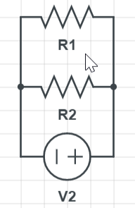
Two resistors of resistance R in parallel will give equal resistance of $dfrac{R}{2}$, as we can see the mentioned circuit in the picture below.
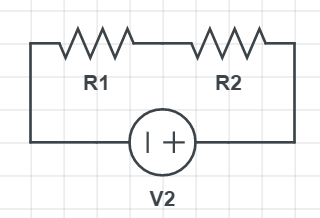
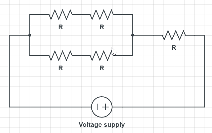
Ideally, the possibility is to make the overall resistance of four resistors $textbf{R}$ and then connect it to one other resistor in series, which will give the desired result of $textbf{2R}$.
Connecting two resistors in series gives 2R, but if we connect two resistors (one branch) in series, parallelly to another two resistors (second branch), we are going to have overall resistance of R, and then we simply add the final resistor in series with first four, which will give 2R. The desired scheme can be found in the picture below:
$$
begin{array}{|c|c|c|c|c|}
hline & mathrm{A} & mathrm{B} & mathrm{C} & mathrm{D} \
hline text { A removed } & – & text { on } & text { on } & text { on } \
hline text { B removed } & text { on } & – & text { on } & text { off } \
hline text { C removed } & text { off } & text { off } & – & text { off } \
hline text { D removed } & text { on } & text { off } & text { on } & – \
hline
end{array}
$$
Firstly, we can analyze, how the two bulbs will behave in serial and parallel circuits and what happens to the overall circuit if only one is removed.
For the lightbulbs connected in the serial circuit, which we can see in the Figure below, if we remove one, we have disconnected the circuit. The current has no way to flow anymore, so neither bulb will light up.
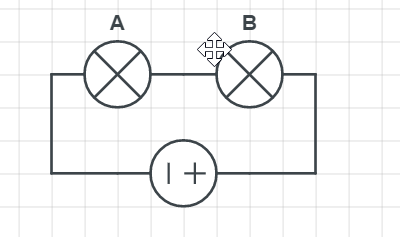
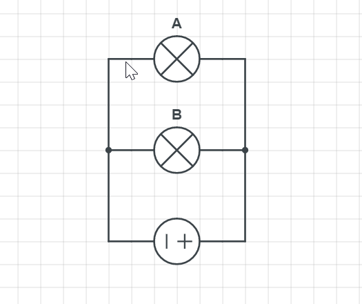
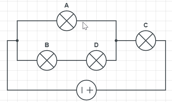
On the other hand, if A is removed, all others are working, which means lightbulbs A is connected in parallel with all other lightbulbs since her removal does not affect any other.
Finally, from the table, we can see that by removing the lightbulbs B or D, we have the same effect on lightbulbs A and C; $textbf{they continue to work}$. Final schematics that correspond to the table can be found below:
$$
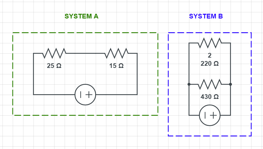
R_{mathrm{eq}}=R_{1}+R_{2} = 15 Omega + 25 Omega
$$
which gives the result of:
$$
R_{mathrm{eq}}=40 Omega
$$
For the $textbf{System B}$ we have the two resistors connected in parallel, the equivalent resistance can be calculated as:
$$
frac{1}{R_{mathrm{eq}}}=frac{1}{R_{1}}+frac{1}{R_{2}}
$$
Putting in the numbers we have:
$$
frac{1}{R_{mathrm{eq}}}=frac{1}{220 Omega}+frac{1}{430 Omega} = frac{1}{0.00687} Omega
$$
which gives the result of:
$$
R_{mathrm{eq}} = 145.54 Omega
$$
mathrm{System A} Rightarrow R_{mathrm{eq}}=40 Omega
$$
$$
mathrm{System B} Rightarrow R_{mathrm{eq}}=145.54 Omega
$$
$$
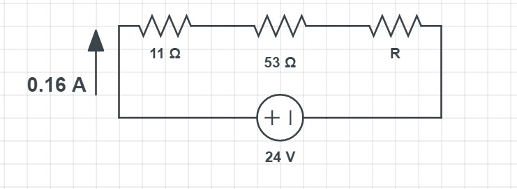
R=frac{U}{I}
$$
Putting in the numbers we have:
$$
R=frac{24 mathrm{V}}{0.16 mathrm{A}}
$$
which gives the result of:
$$
R= 150 Omega = R_{eq}
$$
Now, since we know the total resistance in the circuit and from the schematics we can see we have the three resistors connected in series, we know that equivalent resistance of 150 $Omega$ from those three resistors is equal to:
$$
R_{mathrm{eq}}=11 Omega+53 Omega+R
$$
Expressing the unknown R from this we have:
$$
R= R_{mathrm{eq}} – 11 Omega-53 Omega = 150 Omega – 11 Omega-53 Omega
$$
Which gives the result of:
$$
boxed{color{#c34632}R= 86 Omega}
$$
R= 86 Omega
$$
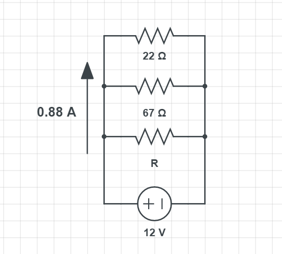
$$
R=frac{U}{I}
$$
Putting in the numbers we have:
$$
R=frac{12 mathrm{~V}}{0.88 mathrm{~A}}
$$
which gives the result of
$$
R=13.64 Omega=R_{e q}
$$
Now that we know the total (equivalent) resistance in the circuit, and seeing from schematics all three resistors are connected in parallel, we can calculate the resistance of the resistor R. For the parallel connection resistance is usually:
$$
frac{1}{R_{mathrm{eq}}}=frac{1}{R_{1}}+frac{1}{R_{2}}+frac{1}{R_{3}}
$$
Adapting the previous relation for the circuit from our problem we have:
$$
frac{1}{R_{mathrm{eq}}}=frac{1}{22 Omega}+{1}{67 Omega}+frac{1}{R} Longrightarrow frac{1}{13.64 Omega} = frac{1}{22 Omega}+{1}{67 Omega}+frac{1}{R}
$$
Expressing the unknown resistance we have:
$$
frac{1}{R}=frac{1}{13.64 Omega}-frac{1}{22 Omega}-frac{1}{67 Omega} = 0.01293
$$
which gives the result for the unknown resistance:
$$
boxed{color{#c34632}R = 77.34 Omega}
$$
R = 77.34 Omega
$$

$$
I = frac{U}{R_{eq}}
$$
where $R_{eq}$ is the equivalent resistance of all three resistors. Since they are connected in series, as it can be seen on the schematics we calculate it, with the following relation:
$$
R_{mathrm{eq}}=R_{1}+R_{2}+R_3
$$
Putting in the numbers we have:
$$
R = 170 Omega + 240 Omega + 65 Omega
$$
which gives the result of:
$$
boxed{R = 475 Omega}
$$
Now using Ohm’s law, as stated before we calculate the current:
$$
I = frac{U}{R_{eq}} = frac{12 mathrm{V}}{475 Omega}
$$
which gives:
$$
boxed{color{#c34632}I = 0.0253 mathrm{A}}
$$
For the $textbf{part b}$ we need to calculate the voltage across each resistor, which we can do again using Ohm’s law:
$$
V1= I cdot R_1= 0.0253 mathrm{A} cdot 170 Omega = boxed{color{#c34632}4.301 mathrm{V}}
$$
$$
V2= I cdot R_2= 0.0253 mathrm{A} cdot 240 Omega = boxed{color{#c34632}6.072 mathrm{V}}
$$
$$
V3= I cdot R_3= 0.0253 mathrm{A} cdot 65 Omega = boxed{color{#c34632}1.645 mathrm{V}}
$$
(a) I = 0.0253 mathrm{A}
$$
$$
(b) V_1 = 4.301 mathrm{V}, V_2 = 6.072 mathrm{V}, V_3 = 1.645 mathrm{V}
$$
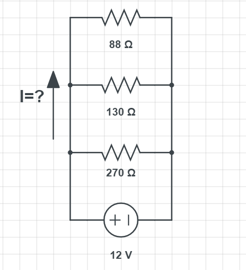
$$
I=frac{U}{R_{e q}}
$$
where $R_{eq}$ is the equivalent resistance of all three resistors, Since they are connected in parallel we use the following relation to calculate the equivalent resistance:
$$
frac{1}{R_{mathrm{eq}}}=frac{1}{R_{1}}+frac{1}{R_{2}}+frac{1}{R_{3}}
$$
Putting in the numbers we have:
$$
frac{1}{R_{mathrm{eq}}}=frac{1}{88 Omega}+frac{1}{130 Omega}+frac{1}{270 Omega} =frac{1}{0.02276 Omega}
$$
Which gives the result of:
$$
{R_{mathrm{eq}}}= 43.94 Omega
$$
Now we can calculate the current:
$$
I=frac{12 mathrm{V}}{43.94 Omega}
$$
We have the result of:
$$
boxed{color{#c34632}I = 0.27 mathrm{A}}
$$
For the $textbf{part b}$ we calculate the current through each resistor. Using Ohm’s law we have:
$$
I_1=frac{U}{R_{1}}= frac{12 mathrm{V}}{88 Omega} = 0.136 mathrm{A}
$$
$$
I_2=frac{U}{R_{2}}= frac{12 mathrm{V}}{130 Omega} = 0.0923 mathrm{A}
$$
$$
I_3=frac{U}{R_{2}}= frac{12 mathrm{V}}{270 Omega} = 0.044 mathrm{A}
$$
(a) I = 0.27 mathrm{A}
$$
$$
(b) I_1= 0.136 mathrm{A}, I_2=0.0923 mathrm{A}, I_3= 0.044 mathrm{A}
$$
,
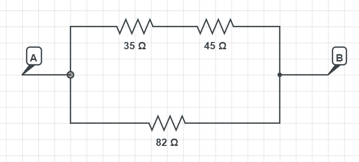
$$
R_{mathrm{eq}}=R_{1}+R_{2}
$$
Putting in the numbers we have:
$$
R_{mathrm{eq}}=35 Omega +45 Omega
$$
which gives:
$$
R_{mathrm{eq}}=80 Omega
$$
Now we calculate the total resistance as the parallel connection of the upper and lower branch:
$$
frac{1}{R_{mathrm{eq}}}=frac{1}{R_{upper}}+frac{1}{R_{lower}}
$$
Putting in the numbers:
$$
frac{1}{R_{mathrm{eq}}}=frac{1}{80 Omega}+frac{1}{82 Omega}= 0.0247 Omega
$$
which gives the final result:
$$
boxed{color{#c34632}R_{mathrm{eq}} = 40.5 Omega}
$$
R_{mathrm{eq}} = 40.5 Omega
$$
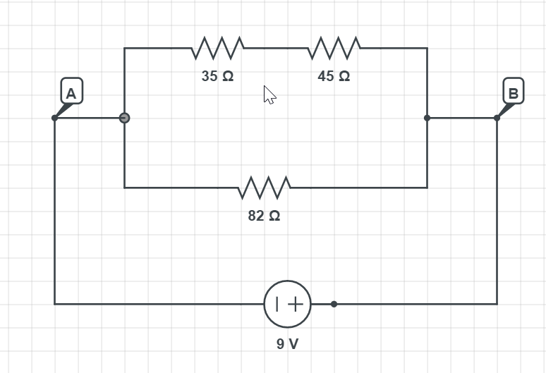
The current that split in the branch must $textbf{equal in the sum}$ to the current that is coming from the source of voltage supply:
$$
I_{source} = I_{upper}+I_{lower}
$$
From the $textbf{Problem 80}$ we have calculated the equivalent resistance for this circuit which is $R_{mathrm{eq}}=40.5 Omega$.
To know the current supplied by the source we use Ohm’s law:
$$
I_{source}= frac{U}{R}
$$
Putting in the numbers we have:
$$
I_{source} = frac{9 mathrm{V}}{40.5 Omega}
$$
which gives the result of:
$$
boxed{I = 0.22 mathrm{A}}
$$
In the lower, we have a voltage of 9 V and resistor of 82 $Omega$, so the current will be:
$$
I_{lower} = frac{U}{R} = frac{9 mathrm{V}}{82 Omega}
$$
which gives the current in a lower resistor:
$$
boxed{color{#c34632}I_{lower} = 0.1098 mathrm{A}}
$$
For the upper branch we simply use the first relation we wrote in the paragraph:
$$
I_{source} = I_{upper}+I_{lower} Longrightarrow I_{upper} = I_{source} – I_{lower}
$$
Putting in the numbers we have:
$$
I_{upper} = 0.22 mathrm{A} – 0.1098 mathrm{A}
$$
We have the result of:
$$
boxed{color{#c34632}I_{upper} = 0.1102 mathrm{A}}
$$
I_{upper} = 0.1102 mathrm{A}
$$
$$
I_{lower} = 0.1098 mathrm{A}
$$

$$
frac{1}{R_{mathrm{eq}}}=frac{1}{R_{1}}+frac{1}{R_{2}}
$$
Putting in the numbers we have:
$$
frac{1}{R_{mathrm{eq}}}=frac{1}{75 Omega}+frac{1}{62 Omega} = 0.02946 Omega
$$
Which gives the equal resistance of:
$$
R_{mathrm{eq}} = 33.94 mathrm{Omega}
$$
To calculate the final resistance we look like we have the two resistors connected in series:
$$
R_{mathrm{eq}}=R_{1}+R_{2} = 24 mathrm{Omega} + 33.94 mathrm{Omega}
$$
Which gives the result of:
$$
boxed{color{#c34632}R_{mathrm{eq}}=57.94 mathrm{Omega}}
$$
R_{mathrm{eq}}=57.94 mathrm{Omega}
$$
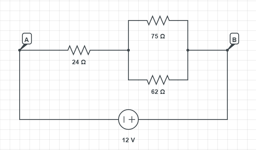
$$
I = frac{U}{R_{eq}}
$$
where $R_{eq}$ is the equivalent resistance of the whole circuit. We have calculated this equivalent resistance in the $textbf{Example 82}$ and it has a value of $R_{mathrm{eq}}=57.94 Omega$. So the current in the whole circuit will be:
$$
I = frac{12 mathrm{V}}{57.94 Omega}
$$
which gives the result of:
$$
boxed{I =I_1 = 0.207 mathrm{A}}
$$
This current of 0.207 A will flow through the first resistor on the left with the resistance of 24 $Omega$. The two resistors on the right, are connected in parallel, so they share the same voltage. We know that voltage on the first resistor is: $U = 24 Omega cdot 0.207 mathrm{A} = 4.968 mathrm{V}$, so the resistors on the right will share a voltage of: $U=12 mathrm{V} – 4.968 mathrm{V}= 7.032 mathrm{V}$.
Since they share voltage and we know their resistance, we can now easily calculate the current using Ohm’s law:
$$
I_2= frac{U}{R_2} = frac{7.032 mathrm{V}}{75 Omega} = boxed{0.0938 mathrm{A}}
$$
$$
I_3= frac{U}{R_3} = frac{7.032 mathrm{V}}{62 Omega} = boxed{0.1134 mathrm{A}}
$$
If the 62 $Omega$ resistor resistance is increased, the overall resistance in the circuit is going to be $textbf{increased}$. This means the battery is going to supply less battery, so the current on the resistor on the left is going to decrease.
Regarding the two resistors on the right, as resistance increases, the voltage on the parallel two resistors is going to increase, which leads to the increased current.
(a) I_1 = 0.207 mathrm{A}, I_2 = 0.0938 mathrm{A}, I_2 = 0.1134 mathrm{A}
$$
$$
(b) text{Decreases on the left resistor, on the two right resistors increases.}
$$
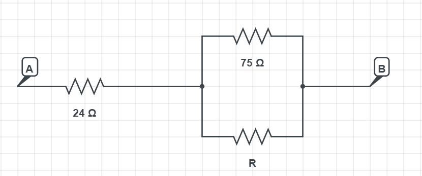
$$
frac{1}{R_{mathrm{eq}}}=frac{1}{75 Omega}+frac{1}{R}
$$
$$
frac{1}{R_{mathrm{eq}}}=frac{1}{75 Omega}+frac{1}{R} = frac{R+75 Omega}{R cdot 75 Omega}
$$
which gives equal resistance for the parallel part:
$$
R_{eq} = frac{R cdot 75 Omega}{R+75 Omega}
$$
Now for the full circuit, we have:
$$
46 Omega = 24 Omega + frac{R cdot 75 Omega}{R+75 Omega}
$$
Simplifying the expression we have:
$$
R cdot 46 Omega + 75 Omega cdot 46 Omega = R cdot 24 Omega + 75 Omega cdot 24 Omega + R cdot 75 Omega
$$
Multiplying everything we have:
$$
R cdot 46 Omega + 3450 Omega^2 = R cdot 24 Omega + 1800 Omega^2 + R cdot 75 Omega
$$
Now solving the equation we are left with:
$$
R cdot 5 Omega =1650 Omega^2
$$
We have the result for resistor R OF:
$$
boxed{color{#c34632}R =frac{1650 Omega^2}{5 Omega} = 330 Omega}
$$
R = 330 Omega
$$
Since we have the power, we can calculate first how much current one lightbulb consumes. The relation for the power is:
$$
P = UI
$$
Expressing the current from this we have:
$$
I = frac{P}{U}
$$
Putting in the numbers we have:
$$
I = frac{65 mathrm{W}}{85 mathrm{V}}
$$
Which gives the current:
$$
I = 0.765 mathrm{A}
$$
To get the maximum numbers of bulbs, we divide our maximum current by the current of the one bulb:
$$
N = frac{2.1 mathrm{A}}{0.765 mathrm{A}}
$$
which gives the result of:
$$
N = 2.745
$$
Our result means that we would need 2.7 bulbs to exceed the maximum current. Since can not have 0.7 of the bulb, only the whole number.
This means if we have 3 lightbulbs we are going to exceed the maximum current in the circuit. So the maximum number of lightbulbs we can use is 2, otherwise, we can fry the circuit or if the circuit is having a fuse it is not going to work.
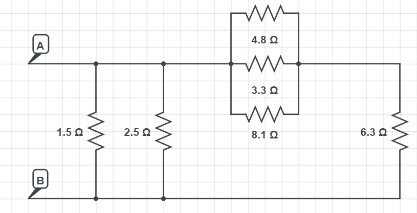
$$
frac{1}{R_{mathrm{eq}}}=frac{1}{R_{1}}+frac{1}{R_{2}}+frac{1}{R_{3}}
$$
Equivalent resistance will be:
$$
R_{mathrm{eq}}=dfrac{1}{dfrac{1}{R_{1}}+dfrac{1}{R_{2}}+dfrac{1}{R_{3}}} = dfrac{1}{dfrac{1}{4.8 Omega}+dfrac{1}{3.3 Omega}+dfrac{1}{8.1 Omega}} = dfrac{1}{0.6348 Omega}
$$
which gives the result of:
$$
R_{mathrm{eqtextbf{1}}}= 1.58 Omega
$$
Now those three resistors in parallel are in series connected with the resistor on the right of 6.3 $Omega$, so we use the relation for the resistors connected in series:
$$
R_{mathrm{eqtextbf{2}}}=R_{eqtextbf{1}}+6.3 Omega = 1.58 Omega + 6.3 Omega
$$
which gives the result of:
$$
R_{mathrm{eqtextbf{2}}} = 7.88 Omega
$$
Now we are left with the circuit as on the schematics below, so we can see we have the three resistors connected in parallel:
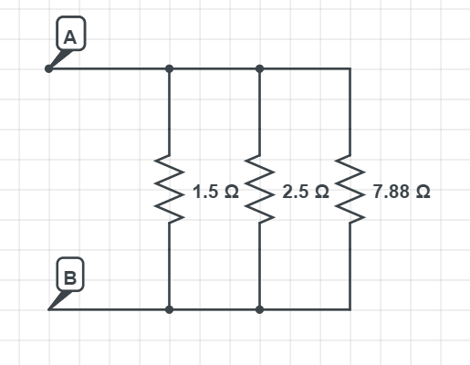
$$
frac{1}{R_{mathrm{eq}}}=frac{1}{R_{1}}+frac{1}{R_{2}}+frac{1}{R_{3}}
$$
Equivalent resistance will be:
$$
R_{mathrm{eq}}=dfrac{1}{dfrac{1}{R_{1}}+dfrac{1}{R_{2}}+dfrac{1}{R_{3}}} = dfrac{1}{dfrac{1}{1.5 Omega}+dfrac{1}{2.5 Omega}+dfrac{1}{7.88 Omega}} = dfrac{1}{0.6348 Omega}
$$
which finally gives the $textbf{equivalent resistance}$ from the starting schematics:
$$
boxed{color{#c34632}R_{mathrm{eq}}= 0.838 Omega}
$$
R_{mathrm{eq}}= 0.838 Omega
$$
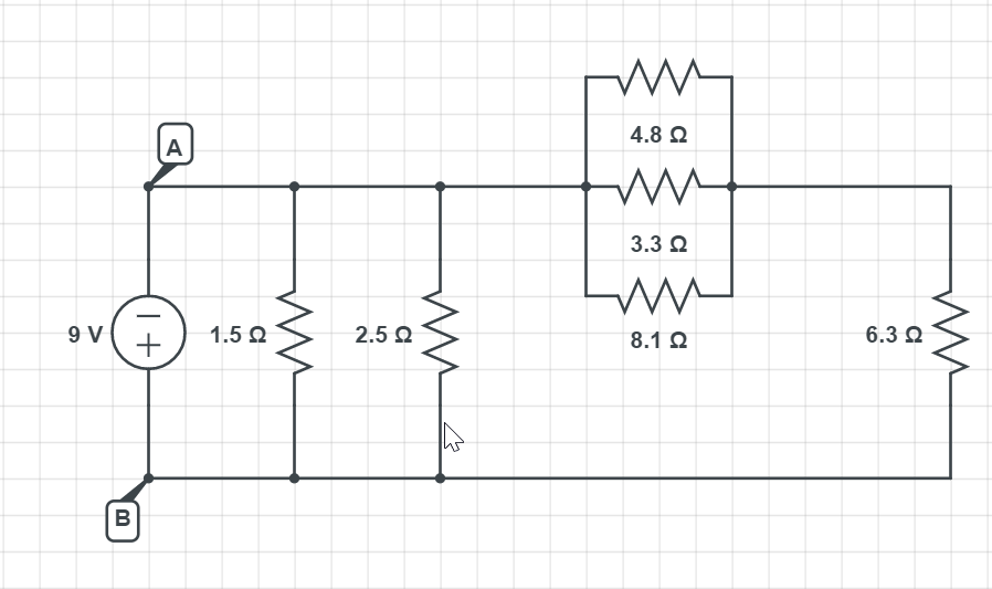
$$
I=frac{U}{R}
$$
$$
I=frac{9 mathrm{V}}{1.5 Omega}
$$
which gives the result of:
$$
boxed{color{#c34632}I= 6 mathrm{A}}
$$
For the $textbf{part b}$ we compare the potential difference on the resistor of 1.5 $Omega$ and the resistor of 6.3 $Omega$. On the first look, it looks like that the resistor of 6.3 $Omega$ directly connected to both terminals of the battery, as the resistor of 1.5 $Omega$, but looking more closely we can see that it is connected with the three resistors in the middle in $textbf{series}$.
Since they are connected in series (the three resistors in parallel and 6.3 $Omega$ resistor), there is a significant voltage drop on it, so the 6.3 $Omega$ resistor has a less potential difference than the 1.5 $Omega$ resistor.
(a) I= 6 mathrm{A}
$$
$$
(b) mathrm{Less.}
$$
In an electric circuit when we know the voltage and resistance, power can be calculated as:
$$
P = frac{V^2}{R}
$$
Applying the parameters from the problem statement we have:
$$
5 cdot P_A = P_B Longrightarrow frac{P_A}{P_B} = frac{1}{5}
$$
putting in the relation for the power:
$$
frac{P_{A}}{P_{B}}=frac{dfrac{V^{2}}{R_{A}}} {dfrac{V^{2}} { R_{B}}} =frac{1}{5}
$$
Since the voltage is constant it cancels out, so we have:
$$
frac{P_{A}}{P_{B}}=frac{R_B}{R_A}=frac{1}{5}
$$
which means:
$$
boxed{color{#c34632}R_A = 5 cdot R_B}
$$
R_A = 5 cdot R_B
$$
We know that power in an electrical circuit when we know the current and voltage can be calculated as:
$$
P = UI
$$
From the problem statement, we know that:
$$
P_A = 3 cdot P_B Longrightarrow UI_A = 3 cdot U I_B
$$
Expressing the ratios we have (voltages can cancel out because they are equal in each case):
$$
frac{P_A}{P_B} = 3 Longrightarrow boxed{color{#c34632}frac{I_A}{I_B}= 3}
$$
frac{I_A}{I_B}= 3
$$
We know that power in an electrical circuit when we know the current and voltage can be calculated as:
$$
P=U I
$$
From the problem statement, we know that:
$$
P_{A}=2 cdot P_{B} Longrightarrow U_{A} I=2 cdot U_{B} I
$$
Expressing the ratios we have (currents can cancel out because they are equal in each case):
$$
frac{P_{A}}{P_{B}}=2 Longrightarrow boxed{color{#c34632}frac{U_{A}}{U_{B}}=2}
$$
frac{U_{A}}{U_{B}}=2
$$
We would like to find out if more power dissipated when they are connected in series or when they are connected in parallel.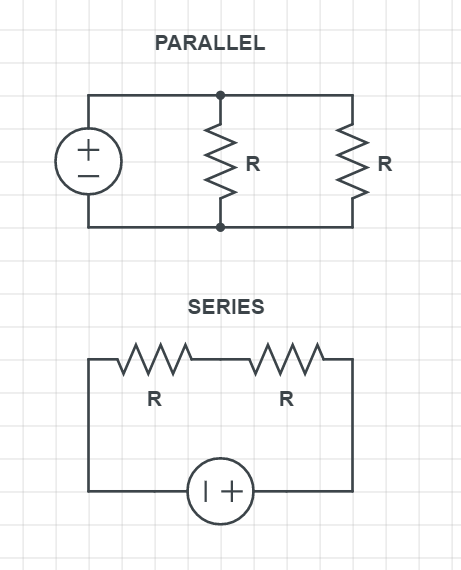
$$
R_{mathrm{eq}}=R_{1}+R_{2}
$$
which means resistors combined in series will always give bigger resistance together, than any individual resistor.
For the resistors connected in parallel we calculate the equivalent resistance with the relation:
$$
frac{1}{R_{mathrm{eq}}}=frac{1}{R_{1}}+frac{1}{R_{2}}
$$
This means that equivalent resistance of resistors in parallel combined will give always less total resistance than each individual resistor.
Now when it comes to the power dissipation, even when starting voltage is equal, we can not exactly determine the current, but we can see that resistance is playing a $textbf{major role}$.
In electric circuits to calculate the power when we know the resistance and voltage, we can use the following relation:
$$
P = frac{V^2}{R}
$$
Since voltage is equal, and resistance is inversely proportional to the power, so less the resistance the more power is the circuit going to dissipate.
We have already shown that in parallel circuit equivalent resistance is always going to be less than the individual resistors, and parallel circuit of resistors will always give less total resistance, compared to the series circuit of resistors (for the same number of resistors of resistance R). So, to conclude, the $textbf{resistors in parallel}$ will dissipate more power.
$$
begin{array}{|c|c|c|}
hline text { System } & text { Current } & text { Resistance } \
hline mathrm{A} & 2 mathrm{I}_{0} & R_{0} \
hline mathrm{B} & mathrm{I}_{0} & 2 R_{0} \
hline mathrm{C} & 4 / 0 & 2 mathrm{R}_{0} \
hline
end{array}
$$
From the problem statement, we know for the current $I_0$ and resistance $R_0$, the power dissipated is 1 W and for this case, we calculate the power with the following relation:
$$
P=I^{2} R Longrightarrow P = {I_0}^2 cdot R_0 = 1 W
$$
For $textbf{System A}$ we have:
$$
P = {(2I_0)}^2 cdot R_0 =4{I_0}^2 cdot R_0 = 4 cdot 1 mathrm{W} = 4 mathrm{W}
$$
For $textbf{System B}$ we have:
$$
P = {I_0}^2 cdot 2 cdot R_0 =2 cdot {I_0}^2 cdot R_0 = 2 cdot 1 mathrm{W} = 2 mathrm{W}
$$
For $textbf{System C}$ we have:
$$
P = {(4I_0)}^2 cdot 2 cdot R_0 =16 cdot {I_0}^2 cdot 2 cdot R_0 = 32 cdot 1 mathrm{W} = 32 mathrm{W}
$$
System B $Rightarrow$ 2 W
System C $Rightarrow$ 32 W
$$
P=frac{V^{2}}{R} Longrightarrow P = frac{{V_0}^2} {R_0} = 1 mathrm{W}
$$
We test the following three systems:
$$
begin{array}{|c|c|c|}
hline text { System } & text { Voltage } & text { Resistance } \
hline mathrm{A} & 2 mathrm{~V}_{0} & R_{0} \
hline mathrm{B} & V_{0} & 2 R_{0} \
hline mathrm{C} & 4 mathrm{~V}_{0} & 2 R_{0} \
hline
end{array}
$$
For $textbf{System A}$ we got:
$$
P = frac{ {2 cdot V_0}^2} {R_0} = frac{{4V_0}^2} {R_0}= 4 cdot 1 mathrm{W} = 4 mathrm{W}
$$
For $textbf{System B}$ we got:
$$
P = frac{ {V_0}^2} {2 cdot R_0} = frac{1}{2} frac{{V_0}^2} { R_0}= frac{1}{2} cdot 1 mathrm{W} = frac{1}{2} mathrm{W}
$$
For $textbf{System C}$ we got:
$$
P = frac{ {4 cdot V_0}^2} {2 cdot R_0} = frac{16}{2} frac{{V_0}^2} { R_0}=8 cdot 1 mathrm{W} = 8 mathrm{W}
$$
System B $Longrightarrow$ $dfrac{1}{2}$ W
System C $Longrightarrow$ 8 W
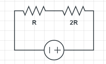
$$
P=I^{2} R
$$
Since the power dissipated is proportional to the resistance, the bigger the resistance of the resistor, the more the current will be dissipated. So for our problem the resistor $R_{2}=2 R$ will dissipate more power.
R_{2}=2 R
$$
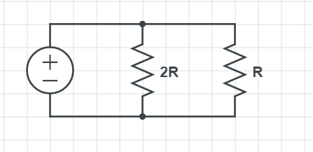
$$
P=frac{V^{2}}{R}
$$
Since the voltage is constant (same for both resistors) we can conclude that the magnitude of the resistance determines the power dissipated. Since in the relation above, resistance is inversely proportional to the power dissipated, it means the bigger the resistance, the less power will be dissipated.
So to find out in our case, which resistor is dissipating more power, it will be the one with a lesser magnitude of resistance, which is $R_{1}=R$
R_{1}=R
$$
$$
P= UI
$$
Expressing current from this we have:
$$
I = frac{P}{U}
$$
And putting in the numbers we have:
$$
I = frac{3.8 times 10^˘{3} mathrm{W}}{75 mathrm{V}}
$$
$$
boxed{color{#c34632}I = 50.67 mathrm{A}}
$$
I = 50.67 mathrm{A}
$$
$$
P=frac{V^{2}}{R}
$$
Expressing voltage form this we have:
$$
V = sqrt{PR}
$$
Putting in the numbers we have:
$$
V = sqrt{140 mathrm{Omega} cdot 2.5 mathrm{W} }
$$
We have the result of:
$$
boxed{color{#c34632}V = 18.71 mathrm{V}}
$$
V = 18.71 mathrm{V}
$$
$$
P=I^{2} R
$$
Expressing the resistance from this we have:
$$
R = frac{P}{I^2}
$$
Putting in the numbers from the problem statement we have;
$$
R = frac{17 mathrm{W}}{{(2.8 mathrm{A})}^2 }
$$
We get the result of:
$$
boxed{color{#c34632}R = 2.17 mathrm{Omega}}
$$
R = 2.17 mathrm{Omega}
$$
the voltage is $V=12$ V. Hence the power dissipated is given by
$$
P=frac{V^{2}}{R}=frac{left(12 {rm V}right)^{2}}{left(0.84 Omegaright)}=171.43 {rm W}
$$
We know that power is related to energy as:$ $P=frac{Delta E}{Delta t}$ $To get how much energy is consumed we have:$ $Delta E = P Delta t$ $Putting in the data from the problem statement we have (we should have in mind that we would like to have energy in kWh because in that unit is our cost expressed):$ $Delta E = 120 times 10^{-3} mathrm{kW} cdot frac{25}{60} mathrm{h}$ $gives the result of:$ $Delta E = 0.05 mathrm{kWh}$ $now since we know the cost per kWh, we calculate the total cost:$ $mathrm{COST} =$0.086 cdot 0.05 mathrm{kWh}$ $which gives:$ $boxed{color{#c34632}mathrm{COST} =$0.0043}$$
mathrm{COST} =$0.0043
$$
To calculate the energy, we will first need to know the power and we calculate with universal power formula for any electric circuit:
$$
P = UI
$$
Putting in the numbers from the problem statement we have:
$$
P = 3.5 mathrm{V} cdot 7.5 times 10^{-3} mathrm{A}
$$
which gives:
$$
P = 0.026 mathrm{W}
$$
Now to get the energy we use the relation:
$$
P=frac{Delta P E}{Delta t},
$$
Expressing the energy from this we have:
$$
Delta P E = P cdot Delta t
$$
Putting in the numbers we got:
$$
Delta P E = 0.026 mathrm{W} cdot 35 mathrm{s}
$$
We have the result of:
$$
boxed{color{#c34632}Delta P E = 0.91 mathrm{J}}
$$
Delta P E = 0.91 mathrm{J}
$$
$$
P=frac{V^{2}}{R}
$$
Putting in the numbers from the problem statement we have:
$$
P=frac{{(15 mathrm{V})}^2}{94 mathrm{Omega}}
$$
We have the result of:
$$
P=2.39 mathrm{W}
$$
Now to calculate the energy we have:
Now to get the energy we use the relation:
$$
P=frac{Delta P E}{Delta t}
$$
Expressing the energy from this we have:
$$
Delta P E=P cdot Delta t
$$
Putting in the numbers we got:
$$
Delta P E=2.39 mathrm{W} cdot 360 mathrm{~s}
$$
We have the result of:
$$
boxed{color{#c34632}Delta P E=860 mathrm{J}}
$$
Delta P E=860 mathrm{J}
$$
For any electric circuit power can universally be calculated as:
$$
P = UI
$$
Putting in the numbers we have:
$$
P = 120 mathrm{V} cdot 3.3 mathrm{A}
$$
which gives:
$$
P = 396 mathrm{W}
$$
For the energy we got:
$$
Delta E=P cdot Delta t = 396 mathrm{W} cdot 1 mathrm{hour} = 0.396 mathrm{kWh}
$$
So we know that $0.396 mathrm{kWh}$ has a price of $textbf{3.8 cents}$.
And cost of electricity at this location in dollars is:
$$
mathrm{COST} = 0.396 times frac{$3.8}{100}
$$
which gives:
$$
boxed{color{#c34632}mathrm{COST} =0.015 $}
$$
mathrm{COST} =0.015 $
$$
$$
P=frac{V^{2}}{R}
$$
Putting in the numbers we have:
$$
P=frac{{(12 mathrm{V})}^2}{45 Omega}
$$
gives the result of:
$$
boxed{P=3.2 mathrm{W}}
$$
For the second resistor we know the current and resistance, we calculate the power with:
$$
P = I^2R
$$
Putting in the numbers from the problem statement, we have:
$$
P = (0.25 mathrm{A})^2 cdot 65 mathrm{Omega}
$$
we have:
$$
boxed{P = 4.06 mathrm{W}}
$$
The energy dissipated is simply calculated as:
$$
Delta E = P Delta t
$$
For the first case we have:
$$
Delta E_1 = 3.2 mathrm{W} cdot 150 mathrm{s} = 480 mathrm{J}
$$
And for the second case we have:
$$
Delta E_1 = 4.06 mathrm{W} cdot 150 mathrm{s} = 609 mathrm{J}
$$
(b) $Delta E_{1}$=480 J, $Delta E_{2}$=609 J
For the $textbf{part a}$ we calculate the current in the bulb:
$$
P = UI Longrightarrow I = frac{P}{U}
$$
Putting in the numbers we have:
$$
I = frac{65 mathrm{W}}{95 mathrm{V}}
$$
which gives the result of:
$$
boxed{color{#c34632}I = 0.684 mathrm{A}}
$$
For the resistance we use Ohm’s law:
$$
R = frac{U}{I} Longrightarrow R=frac{95 mathrm{V}}{0.684 mathrm{A}}
$$
we got:
$$
R = 138.88 Omega
$$
For the $textbf{part c}$ we look at what happens if replace the bulb that has the half resistance of what we calculated. We know the relation connecting power, voltage and resistance is:
$$
P=frac{V^{2}}{R}
$$
We can see if cut the resistance in half, power will be bigger than 65 W. Power will go up by a factor of 2, because it is inversely proportional to the resistance.
(a) I = 0.684 mathrm{A}
$$
$$
(b) R = 138.88 Omega
$$
$$
(c) text{Bigger, by factor of 2.}
$$
$I=905$ A
$V=7.2$ V
and
$t=30$ s.
Hence the energy is
$$
E=IVt=left(905 {rm A}right)left(7.2 {rm V}right)left(30 {rm s}right)=1.9times10^{5} {rm J}
$$
For reserve capacity we have
$I=25$ A
$V=10.5$ V
and
$t=155$ min $=9.3times10^{3}$ s
Hence the energy is
$$
E=IVt=left(25 Aright)left(10.5text{ A}right)left(9.3times10^{3} {rm s}right)=2.44times10^{6}
$$
Hence the reserve capacity represents more energy.
{
$$
R_{mathrm{eq}}=R_{1}+R_{2}+R_{3}
$$
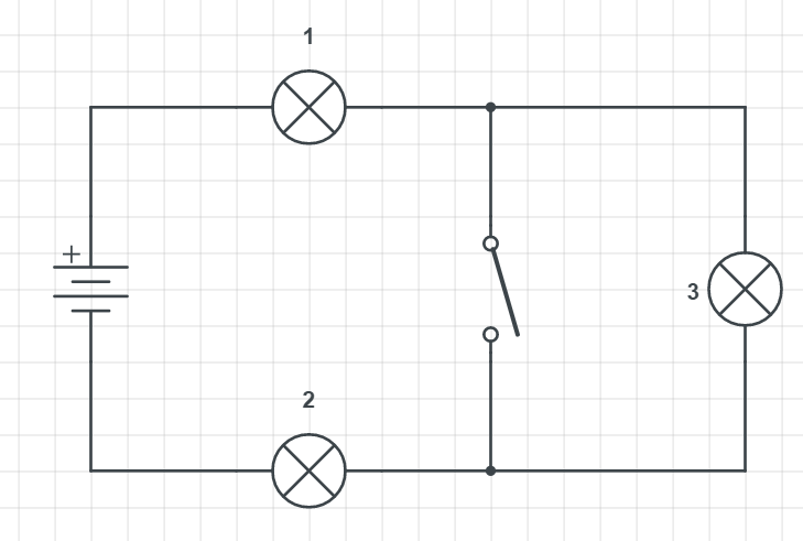
When we close the switch, we can see that the current is then traveling on the unintended path, in another word, the light 3 is $textbf{shorted}$ (short-circuited). When it is shorted no current is going through it, so its light decreases fully.
For the $textbf{part b}$ we consider what happens with lights 1 and 2. Closing the switch will still allow the current to go through. Light 3 is out of consideration, so we realize it affects overall resistance in the circuit which is now 2R.
Since the resistance has reduces the current will change. Because the bigger the current the stronger light will shine. I f we look at Ohm’s law:
$$
I = frac{U}{R}
$$
We see that the current is inversely proportional to the resistance. Less the resistance, the higher the magnitude of the current will be, which means the intensities of the lights 1 and 2 $textbf{will increase}$.
(b) Increases.
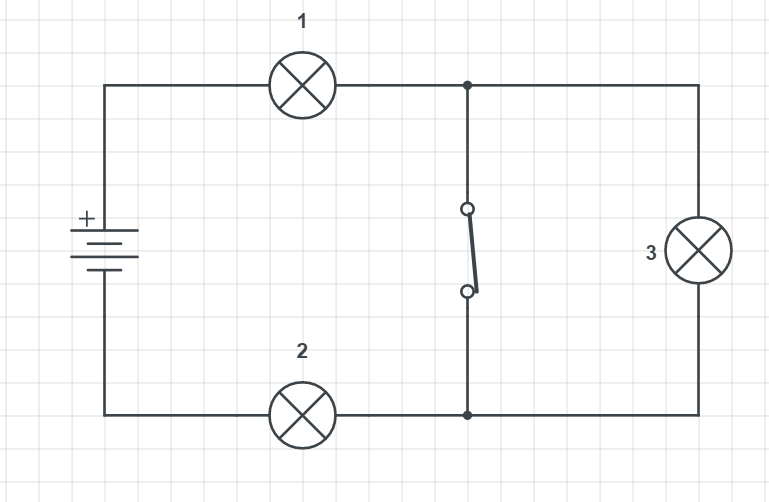
Since by Ohm’s law, $I=dfrac{U}{R}$, the current is inversely proportional to the resistance, the current will be higher in magnitude when the switch is closed, so current supplied by the battery $textbf{increases}$.
For the $textbf{part b}$ correct explanation is under $textbf{C}$.
$textit{Closing the switch shorts out light 2, decreases the
total resistance of the circuit and increases the current.}$
As already mentioned for the explanation in part a, total resistance drops down and is calculated in serially connected resistors as:
$$
R_{mathrm{eq}}=R_{1}+R_{2}
$$
Trough the shorted light there is no flow of the current and all the current (which is increased) is going through the light 1 and 2.
(b) C.
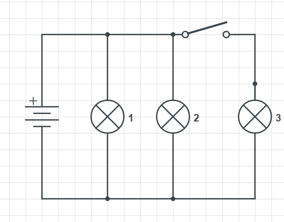
If we look at the schematics light 3 is not in a closed circuit, so it is not shining at all. Now, when the switch is closed, light 3 is also in a closed circuit and current can flow through it, so we definitely know that the intensity of a light 3 is going to increase.
For the $textbf{part b}$ regarding the light 1 and 2, they will $textbf{stay the same}$. We know they are staying the same because of the connection in parallel and it means they are all on the same potential difference given by the battery. Also in the problem statement, we know all the lights have the same resistance, but even without knowing that we know that due to the connection in parallel they remain in the same state (lights 1 and 2).
(b) Stay the same.
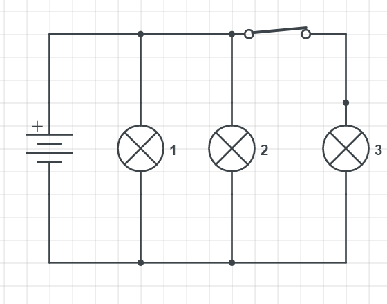
For the $textbf{part b}$ as now, light 3 is included in the circuit. Light 3 is now in the enclosed circuit, so overall the circuit is draining the battery more, than when the switch was opened.
So the explanation A suits best:
$$
textit{The current increases because three lights are drawing current from the battery when the switch is closed, rather than just two.}
$$
(b) A.
To solve this problem, we should remember that we need to use the SI units (as 1 A = 1 $frac{C}{s}$). So 0.75 h is equal to the 45 minutes, which is 45*60 s = 2700 s.
To calculate the current, we use the relation:
$$
I=frac{Delta Q}{Delta t}
$$
Putting in the numbers we have:
$$
I = frac{85 times 10^{-6} mathrm{C}}{2700 mathrm{s}}
$$
Which gives the result of:
$$
boxed{color{#c34632}I = 3.15 times 10^{-8} mathrm{A}}
$$
I = 3.15 times 10^{-8} mathrm{A}
$$
like a short. Hence no current will flow through right side resistance
R. Hence the current will be
$$
I_{A}=frac{varepsilon}{2R}
$$
But in case B, the doide is reversed biased and hence it will behave
like a open circuit. So current will flow through all three resistance
and hence the current will be
$$
I_{B}=frac{varepsilon}{3R}
$$
Hence the current in the circuit A is greater than the circuit B.
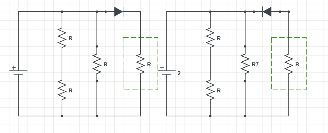
Carefully analyzing both circuits we can see they share all of the same properties, except how the diode is oriented (biased). In-circuit on the left (circuit A) we have a $textbf{forward biased}$ diode, while the circuit on the right (circuit B) has a $textbf{reversed biased diode)}$.
Since for circuit B, the diode is reversed biased it will not allow current to pass through it which has a consequence it does not pass through the resistor R in the green rectangle, as shown on the schematics. Since there is less resistance and this resistor in the green will not drain power from the battery, it takes less current for the circuit B on the right.
While for circuit A on the left, the diode is forward biased and the resistor in the green rectangle will be included (current will be passing through it, which means overall current from the battery is going to be bigger, then for the circuit B.
$$
R=R_{0}left[1+alphaleft(T-T_{0}right)right]
$$
where $alpha$ is the resistance parameter. For the $textbf{part a}$, when filament heats up power is going to decrease. The reason for this is the constant voltage and how do we calculate the power in the circuit with the constant voltage..
Regarding $textbf{part b}$ the explanation A is the correct one:
$textit{The voltage is unchanged, and therefore an increase in resistance implies a reduced power, as we can see
from $P=V^{2} / R$}$.
As it is already shown, the relation how we calculate the power. Since the resistance increases and the resistance is inversely proportional to the power, power is going to decrease $Longrightarrow P=V^{2} / R$.
(b) A.
In this case we can see that the power dissipation is given by
$$
P=I^{2}R
$$
From the equation we can see that the resistor having highest resistance
will dissipate maximum power. Hence the resistane $2R$ will dissipate
most power.
the resistors are same. In this case the power dissipation is given
by
$$
P=frac{V^{2}}{R}
$$
Hence we can see that in this case the power is inversely proportional
to the resistance. So decreasing resistance will increase power. Hence
the $frac{1}{2}R$ resistor will dissipate most power.
First, we remember the relation connecting voltage, power and resistance:
$$
P_1=frac{V^{2}}{R}
$$
We can see power is inversely proportional to the resistance, which means less the resistance, the power will be bigger. When we connect them in series, power will be less than 1000 W.
Since those heaters are having some resistance, when connected in series, the total resistance is going to rise up. Bigger resistance will give less power (as to inverse proportionality).
We can show this as the power is at first 500 V. If we put in the relation, the resistance will be:
$$
R_1=frac{V^{2}}{500 mathrm{W}}
$$
Now connecting both resistors, we double the resistance (assuming they have the same resistance):
$$
R_{1, 2} = 2 cdot frac{V^{2}}{500 mathrm{W}}
$$
Now the power of the two heaters together will be (assuming they have equal resistances):
$$
P_{1,2}=frac{V^{2}}{R_{1.,2}} = frac{V^{2}}{2 cdot dfrac{V^{2}}{500 mathrm{W}}}
$$
which gives fourth times less power:
$$
P_{1,2}= 250 mathrm{W}
$$
$textit{The voltage is the same, but the resistance is doubled by connecting the heaters in series. Therefore, the power consumed ($P = frac{V^2}{R}$) is less than 1000 W.}$
(b) B.
So the resistance will be $667 Omega$. Now the $431 Omega$ will
be in parallel combination with above. So the overall resistance will
be
$$
R=frac{left(667 Omegaright)left(431 Omegaright)}{left(667 Omegaright)+left(431 Omegaright)}=255.07 Omega
$$
in series connection. Hence the equivalent resistance of the circuit
is
$$
R_{eq}=2R=2left(55 Omegaright)=110 Omega
$$
And the voltage is
$$
V=varepsilon=12 {rm V}
$$
So the current in the circuit is
$$
I=frac{V}{R_{eq}}=frac{12 {rm V}}{110 Omega}=0.11 {rm A}
$$
resistance. Hence the current will flow through the resistance.
The first two resistance are connected in series, so the equivalent
resistance is
$$
R_{1}=2R
$$
Now the other resistance are connected to $R_{1}$ in parallel. So
if the equivalent resistance is $R_{eq}$, then we have
$$
frac{1}{R_{eq}}=frac{1}{2R}+frac{1}{R}+frac{1}{R}=frac{5}{2R}
$$
or
$$
R_{eq}=frac{2}{5}R=frac{2}{5}left(62 Omegaright)=24.8 Omega
$$
And the potential difference is $V=varepsilon=24 {rm V}$, so the
current is
$$
I=frac{V}{R_{eq}}=frac{24 {rm V}}{24.8 Omega}=0.99 {rm A}
$$
$$
P=frac{V^{2}}{R_{1}}=frac{left(120 {rm V}right)}{R_{1}}=75.0 {rm W}
$$
So the resistance is
$$
R_{1}=frac{left(120 {rm V}right)^{2}}{75.0}=192 {rm Omega}
$$
we have
$$
begin{align*}
& P=VI\
Rightarrow & I=frac{P}{V}=frac{left(50 {rm W}right)}{120 {rm V}}=0.42 {rm A}
end{align*}
$$
Again we know that the current is given by
$$
I=frac{V}{R}=frac{V}{R_{1}+R_{2}}=frac{120 {rm V}}{R_{2}+left(192 {rm Omega}right)}=0.42 {rm A}
$$
or
$$
R_{2}=93.7 {rm Omega}
$$
will flow through $R_{2}$. Hence the power is
$$
P=frac{V^{2}}{R_{2}}=frac{left(120 {rm V}right)^{2}}{93.7 {rm Omega}}=154 {rm W}
$$
both resistor will be same. Hence the resistance of the first resistor
is
$$
R_{1}=frac{V_{1}}{I}=frac{2.7 {rm V}}{0.15 {rm A}}=18 Omega
$$
The voltage drop across the second resistance is
$$
V_{2}=varepsilon-V_{1}=left(12.0 {rm V}right)-left(2.7 {rm V}right)=9.3 {rm V}
$$
Hence the resistance is
$$
R_{2}=frac{V_{2}}{I}=frac{9.3 {rm V}}{0.15 {rm A}}=62 Omega
$$
So the energy used to change the temperature of water is
$$
Q=mcleft(T_{2}-T_{1}right)=left(4.6 {rm kg}right)left(4.19times10^{3} {rm J/left(kg.text{textdegree} Cright)}right)left(32text{textdegree} C-22text{textdegree} Cright)=1.93times10^{5} {rm J}
$$
Time required is $t=3.8 {rm min}=228 {rm s}$. So the power of
the coil is
$$
P=frac{Q}{t}=frac{left(1.93times10^{5} {rm J}right)}{left(228 {rm s}right)}=846 {rm W}
$$
So the potential difference is
$$
V=sqrt{PR}=sqrt{left(846 {rm W}right)left(250 {rm Omega}right)}=460 {rm V}
$$
across each resistance will be equal to $V=6.0 {rm V}$. Now since
the current through the first resistor is $I_{1}=0.45 {rm A}$.
The resistance of the resistor is
$$
R_{2}=frac{V}{I_{2}}=frac{6.0 {rm V}}{0.45 {rm A}}=13 Omega
$$
When connected in series the potential drop across $R_{2}$ is $V_{2}=left(6.0 {rm V}right)-left(4.0 {rm V}right)=2.0 {rm V}$.
Hence the current through the circuit is
$$
I=frac{V_{2}}{R_{2}}=frac{2.0 {rm V}}{13 Omega}=0.15 {rm A}
$$
So resistance of $R_{1}$ is
$$
R_{1}=frac{V_{1}}{I}=frac{4.0 {rm V}}{0.15 {rm A}}=27 Omega
$$
There are many other semiconductors, but these are the ones mostly used. The special properties of semiconductors are that their resistivity is temperature depended. The higher the temperature, the lower is the resistivity and conductance are rising.
Semiconductors are playing a huge role in the industry and enormous amounts of money are invested in the production and research of semiconductors. They can be chemically manipulated (their crystal structure) so impurities or adding more atoms can increase their conductivity, because in semiconductors $textbf{electrons can be current charge carrier, but holes as well}$. Semiconductor and its application transistor and its working principle are direct consequences of the quantum mechanics theory. The closest semiconductors to anyone currently reading this is exactly the silicon, because it is present in the transistors in our computer processors, and there is a million of them.
This property was discovered by Dutch physicist Kamerlingh-Onnes on the mercury. Today, many superconductors are classified, but the biggest challenge that exists is that they operate at low (cryogenic) temperatures. Discovering room-temperature superconductors would fundamentally affect our energy consumption and the technology we use.
Superconductivity is also a phenomenon that is explained by quantum mechanics and the most commonly known is the BCS theory of superconductivity. Even today there are devices that operate based on superconductivity, but still, their application is not trivial to achieve as everything needs to be at very low temperatures.
Both semiconductors and superconductors are presenting today’s major role in our everyday life and many investments are channeled into the research and development of these materials. Potential applications of superconductivity are endless, but even today they are already present in medicine (NMR) to the power levitating trains to the fusion reactors.
resistance is $V=3.70 {rm V}$. Hence the current is
$$
I=frac{V}{R}=frac{3.70 {rm V}}{1.00times10^{6} Omega}=3.7times10^{-6} {rm A}
$$
Correct answer is A.
And the current through the circuit is $I=3.7times10^{-6}$ A. Hence
the resistance is
$$
R=frac{V}{I}=frac{46.3}{3.7times10^{-6}}=1.25times10^{7} Omega
$$
The correct answer is A.
$$
R_{eq}=left(1.00times10^{6} {rm Omega}+4.00times10^{7} Omegaright)=4.1times10^{7} Omega
$$
Now the current through the circuit is
$$
I=frac{V}{R_{eq}}=frac{50 {rm V}}{4.1times10^{7} Omega}=1.22times10^{-6} {rm A}
$$
Hence the voltage across resistance $R$ is
$$
V=IR=left(1.22times10^{-6} {rm A}right)left(1.00times10^{6} Omegaright)=1.22 {rm V}
$$
Hence the correct answer is B.
That is how we know that resistance is decreased (also in the parallel circuit we know that equal resistance is always less than each individual resistor). From Ohm’s law:
$$
I = frac{U}{R}
$$
we know that resistance will be less and current is going to increase. A consequence of all this is that voltmeter is going to give an increased reading, as well.
