All Solutions
Page 629: Assessment
b) The fish will see him farther away since the rays coming from him refract towards the normal and intersect farther. So the fish would see him at the vicinity of the point 4.
$$
n=frac{c}{v}
$$
yielding
$$
v=frac{c}{n} = frac{3times10^8text{ m/s}}{1.62} = 1.85times10^8text{ m/s}.
$$
$$
n=frac{c}{v}=frac{3times10^8text{ m/s}}{2.14times10^8text{ m/s}}=1.40.
$$
$$
v=frac{d}{t} = frac{0.960text{ m}}{4.00times10^{-9}text{ m}} = 2.4times10^8text{ m/s}.
$$
Now from the definition we directly calculate
$$
n=frac{c}{v}=frac{3times10^8text{ m/s}}{2.4times10^8text{ m/s}} = 1.25.
$$
$$
n_1sinalpha_1=n_2sinalpha_2.
$$
This yields
$$
sinalpha_2=frac{n_1}{n_2}sinalpha_1
$$
and finally
$$
alpha_2=arcsinleft(frac{n_1}{n_2}sinalpha_1right) = arcsinleft(frac{1.25}{1.62}sin43^circ right) =31.75^circ.
$$
$$
n_1sinalpha_1=n_2sinalpha_2.
$$
This directly gives
$$
n_2=frac{n_1sinalpha_1}{sinalpha_2} = frac{1.55sin33^circ}{sin24^circ} =2.08.
$$
$$
n_{air}sinalpha_1=n_{water}sinalpha_2.
$$
Putting $n_{air} = 1$ we get
$$
sinalpha_1=1.33sinalpha_2Rightarrow alpha_1=arcsinleft(1.33sinalpha_2right)=arcsinleft(1.33sin41^circright).
$$
This is finally
$$
alpha_1 = 60.76^circ.
$$
$$
sinalpha_1 = nsinalpha_2.
$$
This yields
$$
n=frac{sinalpha_1}{sinalpha_2} = 1.76.
$$
$$
sinalpha_1=nsinalpha_2.
$$
This yields
$$
n=frac{sinalpha_1}{sinalpha_2}.
$$
Substituting values for the first measurement we have
$$
n=frac{sin10.0^circ}{sin8.00^circ} = 1.25,
$$
and the error is
$$
delta n=frac{1.25-1.33}{1.33} = -6.01%
$$
Substituting values for the second measurement we have
$$
n=frac{sin20.0^circ}{sin15.5^circ} = 1.28,
$$
and the error is
$$
delta n=frac{1.28-1.33}{1.33} = -3.76%.
$$
b) From the Snell’s law we have
$$
n_1sinalpha_1=n_2sinalpha_2.
$$
This yields
$$
sinalpha_2=frac{n_1}{n_2}sinalpha_1
$$
and finally
$$
alpha_2=arcsinleft(frac{n_1}{n_2}sinalpha_1right)=arcsinleft(frac{1,33}{1.66}sin51^circright) = 38.51^circ.
$$
$$
sintheta = nsinvarphi
$$
where $varphi$ is the angle of refraction.
From the triangle in the figure we have
$$
tanphi = frac{5text{ cm}}{20text{ cm}}=frac{1}{4}Rightarrow varphi=arctanfrac{1}{4} = 14^circ.
$$
Now we have
$$
theta=arcsin(nsinphi) = arcsin(1.52sin14^circ) =21.6^circ.
$$
$$
sinalpha_i = frac{W}{sqrt{W^2+H^2}}
$$
and for the angle of refraction we have
$$
sinalpha_r = frac{frac{W}{2}}{sqrt{left(frac{W}{2}right)^2+H^2}} = frac{W}{sqrt{4H^2+W^2}}.
$$
From the Snell’s law we have
$$
sinalpha_i=nsinalpha_rRightarrow frac{W}{sqrt{W^2+H^2}} = 1.33frac{W}{sqrt{4H^2+W^2}}.
$$
The last equation yields
$$
frac{4H^2+W^2}{W^2+H^2}=1.33^2.
$$
This the gives
$$
4H^2+W^2 = 1.33^2W^2+1.33^2H^2Rightarrow H^2(4-1.33^2) = W^2(1.33^2-1).
$$
This is finally
$$
H^2=frac{W^2(1.33^2-1)}{4-1.33^2} Rightarrow H=Wsqrt{frac{1.33^2-1}{4-1.33^2}} =3.64text{ cm}.
$$
b) Luckily, the Earth has an atmosphere. We would expect that the average number everywhere would be $12$ daylight hours but due to refraction of light it is bent so we see it longer. Thus the answer is there is a bit more than $12$ daylight hours everywhere on average during the course of the year.
$$
theta_c=arcsinleft(frac{n_{air}}{n_{water}}right) = arcsinleft(frac{1}{1.33}right) =48.75^circ.
$$
$$
theta_c=arcsin(frac{n_{material}}{n_{water}}).
$$
Taking sine from both sides we get
$$
sintheta_c = frac{n_{material}}{n_{water}}Rightarrow n_{material} = n_{water}sintheta_c = 1.33sin81^circ = 1.31.
$$
$$
begin{align*}
n_1 &= 1.42 \
n_2 &= 1.31
end{align*}
$$
The critical angle for total internal reflection for the two boundaries can be obtain by applying the relation for critical angle :
$$
begin{align*}
sin theta_c &= dfrac{n_2}{n_1} \
theta_c &= {sin}^{-1} left( dfrac{n_2}{n_1} right) \
&= {sin}^{-1} left( dfrac{1.31}{1.42} right)
end{align*}
$$
$$
{boxed{theta_c = 67.3 text{textdegree}}}
$$
Therefore, the total internal reflection occur for $textbf{substance 2}$.
$textbf{substance 2}$
$$
sin32.25^circ = 1.650sinalpha_{red};quad sin32.25^circ =1.670sinalpha_{blue}.
$$
These equations yield
$$
sinalpha_{red}=frac{sin32.25^circ}{1.650};quad sinalpha_{blue} = frac{sin32.25^circ}{1.670}
$$
which is finally
$$
alpha_{red}=arcsinleft(frac{sin32.25^circ}{1.650}right) =18.87^circ;quad alpha_{blue}=arcsinleft(frac{sin32.25^circ}{1.670}right) =18.63^circ.
$$
The angle between the rays is
$$
Deltaalpha=alpha_{red}-alpha_{blue} = 0.24^circ = 14′ 24”.
$$
$$
begin{align*}
n_2 = n_{air} &= 1 \
theta_c &= 45 text{textdegree}
end{align*}
$$
For total internal reflection, a ray of light travels from air to prism then reflect the light back on air. Upon entering, the light strikes at $45 text{textdegree}$ then reflecting it back at $90 text{textdegree}$, causing a total internal reflection. So applying the total internal reflection expression to the problem to calculate for the prism’s index of refraction, $n_1$ :
$$
{sin theta_c = dfrac{n_2}{n_1}}
$$
$$
{n_1 = dfrac{n_2}{sin theta_c}}
$$
$$
{n_1 = dfrac{1}{sin 45 text{textdegree}}}
$$
$$
{boxed{n_1 = 1.414}}
$$
{n_1 = 1.414}
$$
$$
begin{align*}
n_1 &= 1.46 \
theta_c &= 44 text{textdegree}
end{align*}
$$
$textbf{(a)}$ The index of refraction for the unknown material should be $textbf{less than}$ to 1.46. It is because total internal reflection occurs only when the beam of light is trying to enter a material from a higher index of refraction to a material of lower index of refraction.
$$
{sin theta_c = dfrac{n_2}{n_1}}
$$
$$
{n_2 = n_1 (sin theta_c)}
$$
$$
{n_2 = 1.46 (sin 44 text{textdegree})}
$$
$$
{boxed{n_2 = 1.0142}}
$$
$textbf{(b)}$ ${n_2 = 1.0142}$
$$
begin{aligned}
theta = 77.5degree
end{aligned}
$$
**Useful equations**
Snell’s law relates the angles of two materials of different index of refraction.
$$
begin{aligned}
n_1 sin theta_1 = n_2 sin theta_2
end{aligned}
$$
Trigonometric identity:
$$
begin{aligned}
sin (90degree – theta) &= cos theta \ cos^2 theta &= 1 – sin^2 theta
end{aligned}
$$
$$
begin{aligned}
(1)sin theta_1 &= n_2 sin theta_2 \ sin theta_2 &= frac{sin theta_1}{n_2} tag{1}
end{aligned}
$$
$$
begin{aligned}
(1)sin theta_1 &= n_2 sin (90degree – sin theta_2) \ sin 90degree &= n_2 cos theta_2 \ n_2 cos theta_2 &= 1
end{aligned}
$$
$$
begin{aligned}
n_2^2 cos^2 theta_2 &= 1 \ n_2^2 (1 – sin_2^2 theta_2) &= 1 \ n_2^2 left(1 – frac{sin^2 theta_1}{n_2^2} right) &= 1 \ n_2^2 – sin^2 theta_1 &= 1
end{aligned}
$$
$$
begin{aligned}
n_2^2 &= sin^2 theta_1 + 1 \ n_2 &= sqrt{sin^2 theta_1 + 1} \ &= sqrt{(sin 77.5degree)^2 + 1} \ &= 1.4
end{aligned}
$$
$$
begin{aligned}
n_2 &= sqrt{sin^2 theta_1 + 1}
end{aligned}
$$
Hence, if we decrease $theta_2$, $sin_2 theta_2$ will decrease which will make the minimum value of $n$ to **decrease.**
$$
begin{aligned}
theta_{text{r}} + theta_{text{i}} = 45degree
end{aligned}
$$
**Useful equations**
Snell’s law relates the angles of two materials of different index of refraction.
$$
begin{aligned}
n_1 sin theta_1 = n_2 sin theta_2
end{aligned}
$$
Trigonometric identity:
$$
begin{aligned}
sin (A – B) &= sin A cos B – cos A sin B \ tan A &= frac{sin A}{cos A}
end{aligned}
$$
$$
begin{aligned}
(1) sin 45degree &= n_2 sin theta_{text{r}} \ n_2 &= frac{sin 45degree}{sin theta_{text{r}}} tag{1}
end{aligned}
$$
$$
begin{aligned}
n_2 sin theta_{text{i}} &= n_3 sin theta_3 \ n_2 sin theta_{text{i}} &= sin 34degree tag{2}
end{aligned}
$$
$$
begin{aligned}
left(frac{sin 45degree}{sin theta_{text{r}}}right) sin theta_{text{i}} &= sin 34degree \ frac{sin theta_{text{i}}}{sin theta_{text{r}}} &= frac{sin 34degree}{sin 45degree} tag{3}
end{aligned}
$$
$$
begin{aligned}
frac{sin (45degree – theta_{text{r}})}{sin theta_{text{r}}} &= frac{sin 34degree}{sin 45degree} \ sin 45degree cos theta_{text{r}} – cos 45degree sin theta_{text{r}} &= left(frac{sin 34degree}{sin 45degree}right) sin theta_{text{r}} \ sin 45degree cos theta_{text{r}} &= left(frac{sin 34degree}{sin 45degree}right) sin theta_{text{r}} + cos 45degree sin theta_{text{r}} \ sin 45degree cos theta_{text{r}} &= sin theta_{text{r}} left(frac{sin 34degree}{sin 45degree} + cos 45degreeright) \ frac{cos theta_{text{r}}}{sin theta_{text{r}}} &= frac{1}{sin 45degree} left(frac{sin 34degree}{sin 45degree} + cos 45degreeright)
end{aligned}
$$
$$
begin{aligned}
tan theta_{text{r}} &= sin 45degreeleft(frac{1}{frac{sin 34degree}{sin 45degree} + cos 45degree}right) \ theta_{text{r}} &= tan^{-1} left[ sin 45degreeleft(frac{1}{frac{sin 34degree}{sin 45degree} + cos 45degree}right)right] \ &= 25.3degree
end{aligned}
$$
$$
begin{aligned}
n_2 &= frac{sin 45degree}{sin 25.3degree} = boxed{1.7}
end{aligned}
$$
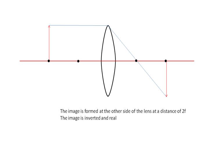
We choose the top of the image as our reference point. From this point, we trace a parallel ray approaching the lens, shown as red-colored ray on the diagram. This ray is then bent so that it passes through the focal point.
The next ray is the midpoint ray where it goes for our reference point through the middle of the lens, shown as blue-colored ray on the diagram.
The last ray is the focal-point ray, shown as green-colored ray on the diagram. This ray goes from our reference point through the focal point and then parallel to the lens. The intersection of these three rays is the location of the image.
Since the image is on the opposite side of the lens and upside-down, it is real and inverted image.
We use the thin-lens equation to find the approximate size and location of the image. The thin-lens equation is given by:
$$begin{align*}
frac{1}{d_{text{o}}} + frac{1}{d_{text{i}}} = frac{1}{f}
end{align*}$$
where $d_{text{o}}$ is the object distance from the lens, $d_{text{i}}$ is the image distance, and $f$ is the focal length of the lens.
$$begin{align*}
frac{1}{d_{text{i}}} = frac{1}{f} – frac{1}{d_{text{o}}}
end{align*}$$
$$begin{align*}
frac{1}{d_{text{i}}} &= frac{1}{12;text{cm}} – frac{1}{25;text{cm}} \ d_{text{i}} &= boxed{23;text{cm}}
end{align*}$$
$$begin{align*}
m = -frac{d_{text{i}}}{d_{text{o}}} = frac{h_{text{i}}}{h_{text{o}}}
end{align*}$$
where $h_{text{i}}$ is the image height and $h_{text{o}}$ is the object height which is given as 6 cm.
$$begin{align*}
frac{d_{text{i}}}{d_{text{o}}} &= frac{h_{text{i}}}{h_{text{o}}} \ h_{text{i}} &= frac{d_{text{i}} h_{text{o}}}{d_{text{o}}}
end{align*}$$
$$begin{align*}
h_{text{i}} = frac{(23;text{cm})(6;text{cm})}{25;text{cm}} = boxed{5.5;text{cm}}
end{align*}$$
The next ray is the midpoint ray, shown as the blue-colored ray on the diagram. This ray goes from the reference point through lens and is directed to the focal point. Since after it passes through the lens, the light is refracted, the ray that is directed to the focal point is a dashed-blue ray.
The last ray is the focal-point ray, shown as the green-colored ray on the diagram. This ray goes from the reference point through the center of the lens. The intersection of the three rays, including the dashed rays, is the location of the image.

The image is at the left side of the lens and it is reduced in size and **upright image**.
We use the thin-lens equation to find the approximate size and location of the image. The thin-lens equation is given by:
$$begin{align*}
frac{1}{d_{text{o}}} + frac{1}{d_{text{i}}} = frac{1}{f}
end{align*}$$
where $d_{text{o}}$ is the object distance from the lens, $d_{text{i}}$ is the image distance, and $f$ is the focal length of the lens.
$$begin{align*}
frac{1}{d_{text{i}}} = frac{1}{f} – frac{1}{d_{text{o}}}
end{align*}$$
$$begin{align*}
frac{1}{d_{text{i}}} = frac{1}{f} – frac{1}{d_{text{o}}}
end{align*}$$
$$begin{align*}
frac{1}{d_{text{i}}} &= -frac{1}{15;text{cm}} – frac{1}{11;text{cm}} \ d_{text{i}} &= boxed{-6.3;text{cm}}
end{align*}$$
**The image location is 6.3 cm on the left side of the lens**.
$$begin{align*}
m = -frac{d_{text{i}}}{d_{text{o}}} = frac{h_{text{i}}}{h_{text{o}}}
end{align*}$$
where $h_{text{i}}$ is the image height and $h_{text{o}}$ is the object height which is given as 5 cm.
$$begin{align*}
-frac{d_{text{i}}}{d_{text{o}}} &= frac{h_{text{i}}}{h_{text{o}}} \ h_{text{i}} &= -frac{d_{text{i}} h_{text{o}}}{d_{text{o}}}
end{align*}$$
$$begin{align*}
h_{text{i}} = -frac{(-6.3;text{cm})(5;text{cm})}{11;text{cm}} = boxed{2.9;text{cm}}
end{align*}$$
**The image height is 2.9 cm**.
We choose the top of the object as the reference point. We trace the parallel ray, shown as the red-colored ray on the diagram, from the reference point parallel to the lens and then bends upward. We also trace the connected ray to the focal point, shown as the dashed-red ray.
The next ray is the midpoint ray, shown as the blue-colored ray on the diagram. This ray goes from the reference point through lens and is directed to the focal point. Since after it passes through the lens, the light is refracted, the ray that is directed to the focal point is a dashed-blue ray.
The last ray is the focal-point ray, shown as the green-colored ray on the diagram. This ray goes from the reference point through the center of the lens. The intersection of the three rays, including the dashed rays, is the location of the image.

The image is at the left side of the lens and it is reduced in size and **an upright image**.
The image is between the lens and the focal point, hence, **the image is virtual**.
$$
begin{align*}
d_o &= 23 text{ cm} \
f &= -32 text{ cm}
end{align*}
$$
$$
begin{align*}
dfrac{1}{d_o} + dfrac{1}{d_i} &= dfrac{1}{f} \
d_i &= dfrac{1}{dfrac{1}{f} – dfrac{1}{d_o}} \
&= dfrac{1}{dfrac{1}{- 32 text{ cm}} – dfrac{1}{23 text{ cm}}} \
d_i &= -13.38 text{ cm}
end{align*}
$$
$$
{m = dfrac{- d_i}{d_o}}
$$
$$
{m = dfrac{13.38 text{ cm}}{23 text{ cm}}}
$$
$$
{boxed{m = 0.582 text{ cm}}}
$$
{m = 0.582 text{ cm}}
$$
$$
begin{align*}
d_o &= 32 text{ cm} \
d_i &= 17 text{ cm}
end{align*}
$$
The image distance from the lens is positive since it is located on the opposite side of where the object is. The focal length of the lens can be calculated by applying the thin-lens equation to the problem :
$$
begin{align*}
dfrac{1}{d_o} + dfrac{1}{d_i} &= dfrac{1}{f} \
f &= dfrac{1}{dfrac{1}{d_o} + dfrac{1}{d_i}} \
&= dfrac{1}{dfrac{1}{32 text{ cm}} + dfrac{1}{17 text{ cm}}}
end{align*}
$$
$$
{boxed{f = 11.1 text{ cm}}}
$$
{f = 11.1 text{ cm}}
$$
$$
begin{align*}
d_o &= 5 text{ m} \
f &= 45.5 text{ mm} \
d &= 35 text{ mm}
end{align*}
$$
The distance from a camera lens to the CCD sensor is equal to the image distance from the lens. This can be calculated by applying the thin-lens equation to the problem :
$$
begin{align*}
dfrac{1}{d_o} + dfrac{1}{d_i} &= dfrac{1}{f} \
d_i &= dfrac{1}{dfrac{1}{f} – dfrac{1}{d_o}} \
&= dfrac{1}{dfrac{1}{45.5 text{ mm}} – dfrac{1}{5000 text{ mm}}}
end{align*}
$$
$$
{boxed{d_i = 45.92 text{ mm}}}
$$
{d_i = 45.92 text{ mm}}
$$
$$
begin{align*}
f &= 36 text{ cm} \
m &= 4
end{align*}
$$
$textbf{(a)}$ In order to increase the value of the magnification to 4.0 from 3.0, the object distance should be moved $textbf{farther away}$ from the lens. As observed from the magnification expression, the object distance is inversely proportional to the magnification value so the farther the object is between the lens and focal point, the greater the magnification of the image.
$$
{m = dfrac{- d_i}{d_o}}
$$
$$
{d_i = -m d_o}
$$
$$
{d_i = -4 d_o}
$$
Applying the thin-lens equation and substitute the known values to the expression :
$$
begin{align*}
dfrac{1}{d_o} + dfrac{1}{d_i} &= dfrac{1}{f} \
dfrac{1}{d_o} + dfrac{1}{-4 d_o} &= dfrac{1}{36} \
dfrac{3}{4 d_o} &= dfrac{1}{36} \
4 d_o &= 3 (36) \
d_o &= dfrac{108 text{ cm}}{4}
end{align*}
$$
$$
{boxed{d_o = 27 text{ cm}}}
$$
$textbf{(b)}$ ${d_o = 27 text{ cm}}$
$$
begin{align*}
d_o &= 21 text{ cm} \
m &= 0.67
end{align*}
$$
$textbf{(a)}$ After your friend takes off his eyeglasses, the image he sees is upright and reduced from its actual size. Referring to Table 17.2, these images shows that the lenses in the eyeglass is a $textbf{concave lens}$.
$$
{m = dfrac{- d_i}{d_o}}
$$
$$
{d_i = -m d_o}
$$
$$
{d_i = -0.67 d_o}
$$
Applying the thin-lens equation and substitute the known values to the expression :
$$
begin{align*}
dfrac{1}{d_o} + dfrac{1}{d_i} &= dfrac{1}{f} \
dfrac{1}{d_o} + dfrac{1}{-0.67 d_o} &= dfrac{1}{f} \
dfrac{-0.493}{d_o} &= dfrac{1}{f} \
f &= dfrac{d_o}{-0.493} \
&= dfrac{21 text{ cm}}{-0.493}
end{align*}
$$
$$
{boxed{f = – 42.6 text{ cm}}}
$$
$textbf{(b)}$ ${f = – 42.6 text{ cm}}$
$$
begin{align*}
d_o &= 21 text{ cm} \
m &= 1.5
end{align*}
$$
$textbf{(a)}$ After your friend takes off his eyeglasses, the image he sees is upright and enlarged from its actual size. Referring to Table 17.2, these images shows that the lenses in the eyeglass is a $textbf{convex lens}$.
$$
{m = dfrac{- d_i}{d_o}}
$$
$$
{d_i = -m d_o}
$$
$$
{d_i = -1.5 d_o}
$$
Applying the thin-lens equation and substitute the known values to the expression :
$$
begin{align*}
dfrac{1}{d_o} + dfrac{1}{d_i} &= dfrac{1}{f} \
dfrac{1}{d_o} + dfrac{1}{-1.5 d_o} &= dfrac{1}{f} \
dfrac{1}{3 d_o} &= dfrac{1}{f} \
f &= 3 d_o \
&= 3 (21 text{ cm})
end{align*}
$$
$$
{boxed{f = 63 text{ cm}}}
$$
$textbf{(b)}$ ${f = 63 text{ cm}}$
$textbf{(b)}$ The best statement is $textbf{B}$. The lens with the positive focal length is a convex or converging lens, it focuses the Sun’s rays into an intense real image that can start a fire.
$textbf{(b)}$ The best statement is $textbf{B}$.
$$
begin{align*}
d_o &= 3.2 text{ m} \
f &= 2.5 text{ cm} \
h &= 1.9 text{ m}
end{align*}
$$
Calculating for the image distance :
$$
begin{align*}
dfrac{1}{d_o} + dfrac{1}{d_i} &= dfrac{1}{f} \
d_i &= dfrac{1}{dfrac{1}{f} – dfrac{1}{d_o}} \
&= dfrac{1}{dfrac{1}{0.025 text{ m}} – dfrac{1}{3.2 text{ m}}} \
d_i &= 0.0252 text{ m}
end{align*}
$$
$$
{m = dfrac{- d_i}{d_o}}
$$
$$
{m = dfrac{- 0.0252 text{ m}}{3.2 text{ m}}}
$$
$$
{m = – 7.874 cdot 10^{-3}}
$$
Therefore, the height of your friend’s image will be :
$$
{H = m h}
$$
$$
{H = |-7.874 cdot 10^{-3}| (1.9 text{ m})}
$$
$$
{boxed{H = 1.5 text{ cm}}}
$$
{H = 1.5 text{ cm}}
$$
$$
begin{align*}
d_i &= 2.6 text{ cm} \
f &= 2.2 text{ cm}
end{align*}
$$
The near point for Uncle Albert is equal to the nearest object distance that his eye can see in order to produce an image of 2.60 cm from his retina. So using the thin-lens equation to calculate for the object distance :
$$
begin{align*}
dfrac{1}{d_o} + dfrac{1}{d_i} &= dfrac{1}{f} \
d_o &= dfrac{1}{dfrac{1}{f} – dfrac{1}{d_i}} \
&= dfrac{1}{dfrac{1}{2.2 text{ cm}} – dfrac{1}{2.6 text{ cm}}}
end{align*}
$$
$$
{boxed{d_o = 14.3 text{ cm}}}
$$
{d_o = 14.3 text{ cm}}
$$
$$
begin{align*}
f_o &= 1600 text{ mm} \
f_e &= 32 text{ mm}
end{align*}
$$
The magnification of a telescope is the ratio of the focal length of the objective to the eyepiece. Therefore the magnification can be calculated as :
$$
{m = dfrac{f_o}{f_e}}
$$
$$
{m = dfrac{1600 text{ mm}}{32 text{ mm}}}
$$
$$
{boxed{m = 50}}
$$
{m = 50}
$$
$$
begin{align*}
d_{o,c} &= 30 text{ cm} \
f_1 &= 20.5 text{ cm} \
d_d &= 70 text{ cm} \
f_2 &= – 42.5 text{ cm}
end{align*}
$$
$$
begin{align*}
dfrac{1}{d_{o,c}} + dfrac{1}{d_{i,c}} &= dfrac{1}{f_1} \
d_{i,c} &= dfrac{1}{dfrac{1}{f_1} – dfrac{1}{d_{o,c}}} \
&= dfrac{1}{dfrac{1}{20.5 text{ cm}} – dfrac{1}{30 text{ cm}}} \
d_{i,c} &= 64.74 text{ cm}
end{align*}
$$
$$
{d_{o,d} = d_d – d_{i,c}}
$$
$$
{d_{o,d} = 70 text{ cm} – 64.74 text{ cm}}
$$
$$
{d_{o,d} = 5.26 text{ cm}}
$$
$$
begin{align*}
dfrac{1}{d_{o,d}} + dfrac{1}{d_{i,d}} &= dfrac{1}{f_2} \
d_{i,d} &= dfrac{1}{dfrac{1}{f_2} – dfrac{1}{d_{o,d}}} \
&= dfrac{1}{dfrac{1}{- 42.5 text{ cm}} – dfrac{1}{5.26 text{ cm}}}
end{align*}
$$
$$
{boxed{d_{i,d} = -4.68 text{ cm}}}
$$
Therefore, the final image is located $- 4.68 text{ cm}$ to the left of the diverging lens.
{d_{i,d} = -4.68 text{ cm}}
$$
$$
begin{align*}
d_{o,c} &= 12 text{ cm} \
f_1 &= 8 text{ cm} \
d_d &= 35 text{ cm} \
f_2 &= – 6 text{ cm}
end{align*}
$$
$$
begin{align*}
dfrac{1}{d_{o,c}} + dfrac{1}{d_{i,c}} &= dfrac{1}{f_1} \
d_{i,c} &= dfrac{1}{dfrac{1}{f_1} – dfrac{1}{d_{o,c}}} \
&= dfrac{1}{dfrac{1}{8 text{ cm}} – dfrac{1}{12 text{ cm}}} \
d_{i,c} &= 24 text{ cm}
end{align*}
$$
$$
{d_{o,d} = d_d – d_{i,c}}
$$
$$
{d_{o,d} = 35 text{ cm} – 24 text{ cm}}
$$
$$
{d_{o,d} = 11 text{ cm}}
$$
$$
begin{align*}
dfrac{1}{d_{o,d}} + dfrac{1}{d_{i,d}} &= dfrac{1}{f_2} \
d_{i,d} &= dfrac{1}{dfrac{1}{f_2} – dfrac{1}{d_{o,d}}} \
&= dfrac{1}{dfrac{1}{- 6 text{ cm}} – dfrac{1}{11 text{ cm}}}
end{align*}
$$
$$
{boxed{d_{i,d} = – 3.88 text{ cm}}}
$$
Therefore, the final image is located $- 3.88 text{ cm}$ to the left of the diverging lens.
{d_{i,d} = – 3.88 text{ cm}}
$$
$$
begin{align*}
f_l &= 21 text{ cm} \
f_r &= 55 text{ cm}
end{align*}
$$
$textbf{(a)}$ The right lens having a focal length of $55 text{ cm}$ should he use as the objective piece.
$$
{m = dfrac{f_o}{f_e}}
$$
$$
{m = dfrac{f_r}{f_l}}
$$
$$
{m = dfrac{55 text{ cm}}{21 text{ cm}}}
$$
$$
{boxed{m = 2.62}}
$$
$textbf{(b)}$ ${m = 2.62}$
$$
begin{align*}
d_{o,1} &= 50 text{ cm} \
f_1 &= 20 text{ cm} \
x &= 115 text{ cm} \
f_2 &= 30 text{ cm}
end{align*}
$$
$$
begin{align*}
dfrac{1}{d_{o,1}} + dfrac{1}{d_{i,1}} &= dfrac{1}{f_1} \
d_{i,1} &= dfrac{1}{dfrac{1}{f_1} – dfrac{1}{d_{o,1}}} \
&= dfrac{1}{dfrac{1}{20 text{ cm}} – dfrac{1}{50 text{ cm}}} \
d_{i,1} &= 33.33 text{ cm}
end{align*}
$$
$$
{d_{o,2} = x – d_{i,1}}
$$
$$
{d_{o,2} = 115 text{ cm} – 33.33 text{ cm}}
$$
$$
{d_{o,2} = 81.67 text{ cm}}
$$
$$
begin{align*}
dfrac{1}{d_{o,2}} + dfrac{1}{d_{i,2}} &= dfrac{1}{f_2} \
d_{i,2} &= dfrac{1}{dfrac{1}{f_2} – dfrac{1}{d_{o,2}}} \
&= dfrac{1}{dfrac{1}{30 text{ cm}} – dfrac{1}{81.67 text{ cm}}}
end{align*}
$$
$$
{boxed{d_{i,2} = 47.42 text{ cm}}}
$$
Therefore, the final image is located $47.42 text{ cm}$ to the right of the second lens.
{d_{i,2} = 47.42 text{ cm}}
$$
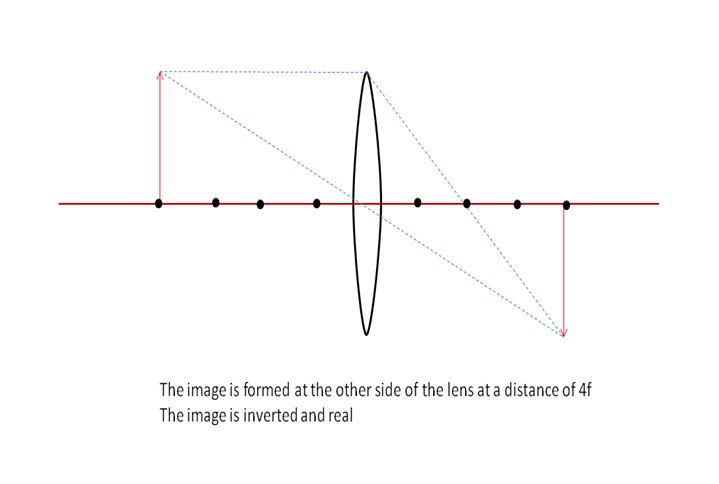
We choose the top of the object as the reference point. There are two lenses so the rays from the first lens will be used for the second lens. Since the first lens is a convex lens, we trace a parallel ray approaching the first lens, shown as red-colored ray on the diagram. This ray is then bent so that it passes through the focal point of the first lens.
The next ray is the midpoint ray where it goes for the reference point through the middle of the first lens, shown as blue-colored ray on the diagram.
The last ray is the focal-point ray, shown as green-colored ray on the diagram. This ray goes from the reference point through the focal point and then parallel to the first lens. The intersection of these three rays is the location of the first image.

The next ray is the midpoint ray, shown as the blue-colored ray on the diagram. This ray goes from the new reference point through the middle of the second lens.
The last ray is the focal-point ray, shown as the green-colored ray on the diagram. This ray goes from the new reference point approaching in parallel the second lens and is then bent downward due to refraction, this ray is extended such that it passes through the focal point of the second lens, as shown by the green-dashed ray. The intersection of the three rays, including the dashed rays, is the location of the final image.
**Hence, the final image is at the left of lens 2**.
The object is beyond the focal point of the lens 1, hence, **the image is inverted**. This is perfectly shown in the diagram from part (a) where the final image has an upside down orientation.
Since the object (the first image) and the second lens 2 are on the same side, **the image is virtual**.
Based on Fig. 17.49, when the object distance is on the left side of the lens, the image distance is negative which means the image is virtual. On the other hand, when the object distance is on the right side of the lens, the image distance is positive and the image is real. Since concave lenses do not produce real images, the shown diagram is a plot of **convex lens**.
When the object is at the focal length, the image is formed at infinity. Based on the plot, when the object is at 0.6 m, the image distance approached infinity. So the focal length of the lens based on the plot is **0.6 m**.
$$
begin{align*}
d_o &= 2.76 text{ cm} \
m &= 2.5
end{align*}
$$
The object distance is equal to the distance that the stamp was held from the lens. Using the magnification relation to calculate for the value of the image distance from the lens :
$$
begin{align*}
m &= dfrac{- d_i}{d_o} \
d_i &= -m d_o \
&= -2.5 (2.76 text{ cm}) \
d_i &= – 6.9 text{ cm}
end{align*}
$$
$$
begin{align*}
dfrac{1}{d_o} + dfrac{1}{d_i} &= dfrac{1}{f} \
f &= dfrac{1}{dfrac{1}{d_o} + dfrac{1}{d_i}} \
&= dfrac{1}{dfrac{1}{2.76 text{ cm}} – dfrac{1}{6.9 text{ cm}}} \
end{align*}
$$
$$
{boxed{f = 4.6 text{ cm}}}
$$
{f = 4.6 text{ cm}}
$$
We choose the top of the image as our reference point. From this point, we trace a parallel ray approaching the lens, shown as red-colored ray on the diagram. This ray is then bent so that it passes through the focal point. We extend this ray to the left side of the lens as dashed-red ray.
The next ray is the midpoint ray where it goes for the reference point through the middle of the lens, shown as blue-colored ray on the diagram. We extend this ray upward until it intersects with the parallel ray.
The intersection of these two rays is the location of the image.

Since the object is between the focal point and the lens, the image formed is virtual, enlarged, and **upright**.
We use the thin-lens equation to find the approximate size and location of the image. The thin-lens equation is given by:
$$begin{align*}
frac{1}{d_{text{o}}} + frac{1}{d_{text{i}}} = frac{1}{f}
end{align*}$$
where $d_{text{o}}$ is the object distance from the lens, $d_{text{i}}$ is the image distance, and $f$ is the focal length of the lens.
$$begin{align*}
frac{1}{d_{text{i}}} = frac{1}{f} – frac{1}{d_{text{o}}}
end{align*}$$
$$begin{align*}
frac{1}{d_{text{i}}} &= frac{1}{15;text{cm}} – frac{1}{7;text{cm}} \ d_{text{i}} &= boxed{-13;text{cm}}
end{align*}$$
**The image location is approximately 13 cm on the left side of the lens**.
$$begin{align*}
m = -frac{d_{text{i}}}{d_{text{o}}} = frac{h_{text{i}}}{h_{text{o}}}
end{align*}$$
where $h_{text{i}}$ is the image height and $h_{text{o}}$ is the object height which is given as 5 cm.
$$begin{align*}
-frac{d_{text{i}}}{d_{text{o}}} &= frac{h_{text{i}}}{h_{text{o}}} \ h_{text{i}} &= -frac{d_{text{i}} h_{text{o}}}{d_{text{o}}}
end{align*}$$
$$begin{align*}
h_{text{i}} = -frac{(-13;text{cm})(5;text{cm})}{7;text{cm}} = boxed{9;text{cm}}
end{align*}$$
**The size of the image is approximately 9 cm**. Indeed, it is an enlarged of the object.
We choose the top of the object as the reference point. We trace the parallel ray, shown as the red-colored ray on the diagram, from the reference point parallel to the lens and then bends upward. We also trace the connected ray to the focal point, shown as the dashed-red ray.
The next ray is the midpoint ray, shown as the blue-colored ray on the diagram. This ray goes from the reference point through lens and is directed to the focal point. Since after it passes through the lens, the light is refracted, the ray that is directed to the focal point is a dashed-blue ray.
The last ray is the focal-point ray, shown as the green-colored ray on the diagram. This ray goes from the reference point through the center of the lens. The intersection of the three rays, including the dashed rays, is the location of the image.

The image formed is reduced and **upright**.
We use the thin-lens equation to find the approximate size and location of the image. The thin-lens equation is given by:
$$begin{align*}
frac{1}{d_{text{o}}} + frac{1}{d_{text{i}}} = frac{1}{f}
end{align*}$$
where $d_{text{o}}$ is the object distance from the lens, $d_{text{i}}$ is the image distance, and $f$ is the focal length of the lens.
$$begin{align*}
frac{1}{d_{text{i}}} = frac{1}{f} – frac{1}{d_{text{o}}}
end{align*}$$
$$begin{align*}
frac{1}{d_{text{i}}} &= -frac{1}{12;text{cm}} – frac{1}{25;text{cm}} \ d_{text{i}} &= boxed{-8.1;text{cm}}
end{align*}$$
**The image location is approximately 8.1 cm on the right side of the lens**.
$$begin{align*}
m = -frac{d_{text{i}}}{d_{text{o}}} = frac{h_{text{i}}}{h_{text{o}}}
end{align*}$$
where $h_{text{i}}$ is the image height and $h_{text{o}}$ is the object height which is given as 6 cm.
$$begin{align*}
-frac{d_{text{i}}}{d_{text{o}}} &= frac{h_{text{i}}}{h_{text{o}}} \ h_{text{i}} &= -frac{d_{text{i}} h_{text{o}}}{d_{text{o}}}
end{align*}$$
$$begin{align*}
h_{text{i}} = -frac{(-8.1;text{cm})(6;text{cm})}{25;text{cm}} = boxed{1.9;text{cm}}
end{align*}$$
**The image size is approximately 1.9 cm**. Indeed, the image formed is reduced.
$$
frac{1}{f}=frac{1}{d_0}+frac{1}{d_i}.
$$
This gives us
$$
frac{1}{d_i}=frac{1}{f}-frac{1}{d_0}Rightarrow frac{1}{d_i} = frac{d_0-f}{fd_0}Rightarrow d_i=frac{fd_0}{d_0-f}.
$$
From the picture we see that
$$
frac{d_0}{h_0}=frac{d_i}{h_i}Rightarrow h_i=h_0frac{d_i}{d_0.}
$$
Substituting here for $d_i$ we have
$$
h_i=h_0frac{frac{fd_0}{d_0-f}}{d_0}=h_0frac{f}{d_0-f} = 1.33text{ cm}.
$$

$$
begin{align*}
d_o &= 74 – 76 text{ cm} \
f &= 30 text{ cm} \
l &= 2 text{ cm}
end{align*}
$$
For the tip of the arrow :
$$
begin{align*}
dfrac{1}{d_{o,1}} + dfrac{1}{d_{i,1}} &= dfrac{1}{f} \
d_{i,1} &= dfrac{1}{dfrac{1}{f} – dfrac{1}{d_{o,1}}} \
&= dfrac{1}{dfrac{1}{30 text{ cm}} – dfrac{1}{74 text{ cm}}} \
d_{i,1} &= 50.455 text{ cm}
end{align*}
$$
For the tail of the arrow :
$$
begin{align*}
dfrac{1}{d_{o,2}} + dfrac{1}{d_{i,2}} &= dfrac{1}{f} \
d_{i,2} &= dfrac{1}{dfrac{1}{f} – dfrac{1}{d_{o,2}}} \
&= dfrac{1}{dfrac{1}{30 text{ cm}} – dfrac{1}{76 text{ cm}}} \
d_{i,2} &= 49.565 text{ cm}
end{align*}
$$
$$
{l_i = d_{i,1} – d_{i,2}}
$$
$$
{l_i = 50.455 text{ cm} – 49.565 text{ cm}}
$$
$$
{boxed{l_i = 0.89 text{ cm}}}
$$
{l_i = 0.89 text{ cm}}
$$
We choose the top of the object as the reference point.For the first lens, we trace a parallel ray approaching the first lens, shown as red-colored ray on the diagram. This ray is then bent upward as it passes through the lens. We extend this bent ray at the left side of lens directly through the focal point as dashed-red ray.
The next ray is the midpoint ray where it goes for the reference point through the middle of the first lens, shown as blue-colored ray on the diagram.
The last ray is the focal-point ray, shown as green-colored ray on the diagram. This ray goes from the reference point through the focal point. On the point of intersection of this ray and the lens, we extend a parallel ray which intersects with the other two rays, this shown as dashed-green ray. The intersection of these three rays is the location of the first image.

The next ray is the midpoint ray, shown as the blue-colored ray on the diagram. This ray goes from the new reference point through the middle of the second lens.
The last ray is the focal-point ray, shown as the green-colored ray on the diagram. This ray goes from the new reference point to the focal point and then parallel as it passes through the second lens. The intersection of the three rays is the location of the final image.
**As shown in the diagram, the final image is at the right of lens 2**.
The object is beyond the focal point of lens 2, hence, the image is **inverted**. This is perfectly shown in the diagram from part (a) where the final image has an upside down orientation.
Since the object (the first image) is beyond the focal point of lens 2, **the image is real**.
$$
begin{align*}
d_{o,1} &= infty \
d_{o,2} &= 50 text{ cm} \
f &= 3 text{ cm}
end{align*}
$$
For an object at infinity :
$$
begin{align*}
dfrac{1}{d_{o,1}} + dfrac{1}{d_{i,1}} &= dfrac{1}{f} \
d_{i,1} &= dfrac{1}{dfrac{1}{f} – dfrac{1}{d_{o,1}}} \
&= dfrac{1}{dfrac{1}{3 text{ cm}} – dfrac{1}{infty}} \
&= dfrac{1}{dfrac{1}{3 text{ cm}} – 0} \
d_{i,1} &= 3 text{ cm}
end{align*}
$$
$$
begin{align*}
dfrac{1}{d_{o,2}} + dfrac{1}{d_{i,2}} &= dfrac{1}{f} \
d_{i,2} &= dfrac{1}{dfrac{1}{f} – dfrac{1}{d_{o,2}}} \
&= dfrac{1}{dfrac{1}{3 text{ cm}} – dfrac{1}{50 text{ cm}}} \
d_{i,2} &= 3.19 text{ cm}
end{align*}
$$
Therefore, the distance will be :
$$
{d = d_{i,2} – d_{i,1}}
$$
$$
{d = 3.19 text{ cm} – 3 text{ cm}}
$$
$$
{boxed{d = 1.9 text{ mm}}}
$$
$$
begin{align*}
d_o &= 45 text{ cm} \
d_i &= 2.9 text{ cm}
end{align*}
$$
$$
begin{align*}
dfrac{1}{d_o} + dfrac{1}{d_i} &= dfrac{1}{f} \
f &= dfrac{1}{dfrac{1}{d_o} + dfrac{1}{d_i}} \
&= dfrac{1}{dfrac{1}{45 text{ cm}} + dfrac{1}{2.9 text{ cm}}} \
end{align*}
$$
$$
{boxed{f = 2.7 text{ cm}}}
$$
