All Solutions
Page 757: Lesson Check
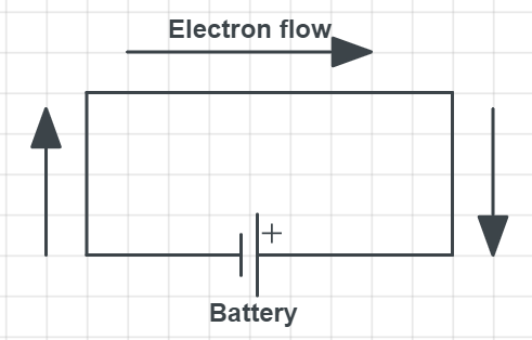
Also, we should comment that circuits like this can easily be shorted, as there is nothing that is consuming current in the circuit. But one should not forget that even the wire has the resistance which allows current normally to flow.

$$
R=frac{V}{I}
$$
expressing the voltage from this we have:
$$
I=frac{V}{R}
$$
since the voltage is constant, from the relation we can see that current is inversely proportional to the resistance, which means that as much as I increase the resistance, for that much current will dropdown. This leads to the conclusion increasing the resistance in the circuit will lower the current.
$$
R=frac{V}{I}
$$
If we have a wire at a temperature of 250 K and 300 K. Resistance at 300 K will be higher and current will be lower, rather than for the temperature of 250 K.
The reason this is happening can be also viewed in the origin of resistance in materials. Resistance is the intrinsic property and temperature is a measure of kinetic energy. So, higher the temperature, atoms inside the material move “more and faster” and due to all collisions and scatterings inside the material, we have a resistance as a result. This activity will be much higher as the temperature is higher.
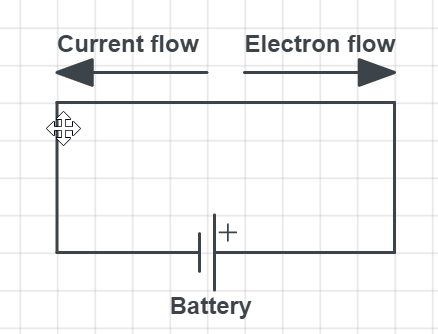
Contrary to this direction of the current is considered different by the convention, than the one explained above. For the current direction, we assume positive charges are moving. So, the real movement of electrons is considered opposite to the considered direction of the current movement.


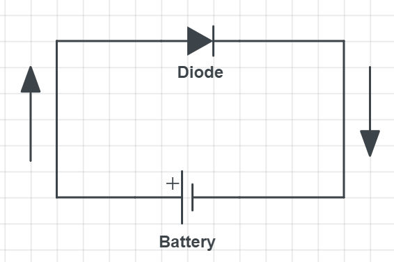
Because of specific $textbf{electronic structure}$ of semiconductors materials, we have a p-type and n-type of semiconductors where electrons or holes can be dominant charge carriers. For our case, if we connect p-type charge carriers can easily flow in the circuit and this is called $textbf{forward biased current}$.

$$
R=frac{V}{I} Rightarrow V=IR
$$
From the problem statement, we know that $R_1= 10 mathrm{Omega}$ and $I_1 = 3 mathrm{~A}$, while $R_2= 5 mathrm{Omega}$ and $I_2 = 10 mathrm{~A}$.
Plugging in the numbers we have:
$$
V_1= I_1R_1 =3 mathrm{~A} cdot 10 mathrm{Omega}
$$
which gives:
$$
V_1= I_1R_1 =boxed{color{#c34632}30 mathrm{~V}}
$$
And for the second voltage we have:
$$
V_2= I_2R_2 =10 mathrm{~A} cdot 5 mathrm{Omega}
$$
we have the result of:
$$
V_2= I_1R_1 =boxed{color{#c34632}50 mathrm{~V}}
$$
We can conclude that resistor 2 has a greater potential difference.
$$
I=frac{V}{R}
$$
Putting in the numbers we have:
$$
I=frac{16 mathrm{~V}}{220 mathrm{~Omega}}
$$
We get the result of:
$$
boxed{color{#c34632}I=0.073 mathrm{~A}}
$$
I=0.073 mathrm{~A}
$$
$$
R=frac{V}{I} Rightarrow V=IR
$$
Putting in the numbers we have:
$$
V=1.8 mathrm{~A} cdot 140 mathrm{~Omega}
$$
We get the result of:
$$
boxed{color{#c34632}V= 252 mathrm{~V}}
$$
V= 252 mathrm{~V}
$$
Since we know the emf and the work needed to be done, we can calculate what amount of charge is being used in this circuit, with the relation for the work done by the battery.:
$$
W=(Delta Q) varepsilon
$$
expressing the charge from the relation above we have:
$$
Delta Q=frac{W} {varepsilon}=frac{150 mathrm{J}}{1.5 mathrm{~V}}
$$
which gives:
$$
Delta Q=100 mathrm{C}
$$
To get the time, we use the relation that defines the current:
$$
I=frac{Delta Q}{Delta t}
$$
Expressing time from this we have:
$$
Delta t=frac{Delta Q}{I} = frac{100 mathrm{C}}{0.44 mathrm{A}}
$$
which gives the result of:
$$
boxed{color{#c34632}Delta t=227.27 mathrm{~A}}
$$
Delta t=227.27 mathrm{~A}
$$
Haven't found what you were looking for?
Search for samples, answers to your questions and flashcards

