
All Solutions
Page 690: Assessment
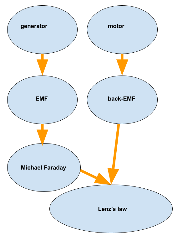
Top left-generator
Second on the right-back EMF
The bottom one-Lenz’s law.
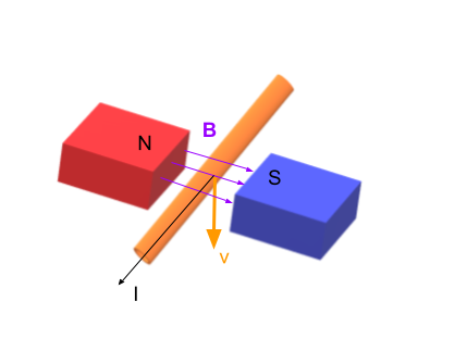
$$
EMF=BLvsintheta
$$
and it will have it’s minimum when $sintheta=0$ and that is achieved when the wire moves parallel with the magnetic field, i.e. when it moves towards us (out of the page).
$$
EMF=BLvsintheta
$$
and we see that it is proportional to the length of the conductor $L$. So if we increase the length of the wire we will increase the voltage (EMF), too.
Motors convert electrical energy into mechanical.
$$
P_{max}=2P_{eff}
$$
This states that
$$
I^2_{max}R=2I^2_{eff}R
$$
Which finally gives that
$$
I_{eff}=0.707I_{max}
$$
$$
EMF=BLv
$$
Where we can express the magnetic field as
$$
B=frac{F}{IL}
$$
and the force is given as $F=ma$ and the current is given as $I=frac{q}{t}$ so we obtain the following
$$
EMF=frac{mcdot acdot Lcdot vcdot t}{qcdot L}=frac{mcdot v^2}{q}
$$
Now, we can use the si units to obtain
$$
boxed{V=frac{textrm{kg}cdot frac{textrm{m}^2}{textrm{s}^2}}{C}=frac{J}{C}}
$$
Which is exactly a definition of volts.
V=frac{J}{C}
$$
$$
EMF=BLv
$$
since the resistance is a physical characteristic of the circuit it will affect only the current since
$$
I=frac{EMF}{R}
$$
$$
P=IV
$$
Once we change the sign of the voltage, the current direction has to change too since
$$
V=IR
$$
and $R>0$ so that means that
$$
P_{inv}=(-V)times (-I)=VI=P
$$
This can be seen by another definition of the power
$$
P=I^2R
$$
Where we see that power is proportional to the square of the current, i.e. it is always positive.
$$
EMF=BLvsintheta
$$
and since $theta=0$ we have that
$$
boxed{EMF=0}
$$
b) Using the third right-hand rule we determine that the force will point up i.e. it will work against the motion of the wire.
b) Up.
a) In the case when the south pole is down, the field lines are exiting the pipe on the north pole and entering the pipe on the south pole. The velocity of the bar is always pointing along the pipe so the current will run around the pipe (the right-hand rule) and not uniformly but close to the south pole the current will be clockwise and near the north pole it will be counterclockwise. In the middle of the bar, there is no current since the field lines are parallel with the pipe, i.e. with the velocity.
b) The induced current will produce a magnetic field which can be imagined as a field of a solenoid, it will be along the pipe. However, this field is not uniform, too. Close to the south pole, it will point down, near the north pole it will point up (the right-hand rule, again).
c) Finally, the main phenomenon is “slow-motion” falling of the bar. One can intuitively say that the forces should cancel out since the fields induced close to the poles point to different directions but the magnet has the poles that oppose to this directions, i.e. south pole will want field lines to go to it and the north pole would have them go from it. Therefore the force will be repelling in both cases.
b) Close to the south pole, the field is pointing down, close to the north pole the field is pointing up.
c) The force is always pointing up.
a) Close to the north pole the magnetic field lines move out of the pipe and with the velocity pointing down, the right-hand rule tells us that the direction of the induced current is $boxed{counterclockwise}$.
2) Now, the current induced creates a magnetic field which will point $boxed{up}$ the pipe, again obtained by the right-hand rule.
b) Up
$$
EMF=BLv
$$
From here, one can express the magnetic field as
$$
B=frac{EMF}{Lv}=frac{40}{20times 4}
$$
Finally, one obtains that
$$
boxed{B=0.5textrm{ T}}
$$
B=0.5textrm{ T}
$$
$$
EMF=BLvsinthetaapprox BLv
$$
Which after we plug in the values gives
$$
EMF=4.5times 10^{-5} times 75times 9.5times 10^2times frac{1000}{3600}
$$
Finally, we have that
$$
boxed{EMF=0.89textrm{ V}}
$$
EMF=0.89textrm{ V}
$$
$$
EMF=BLv
$$
From here, one can express the speed of the wire as
$$
v=frac{EMF}{BL}=frac{10}{2.5times 0.2}
$$
Finally, one obtains that
$$
boxed{v=20frac{textrm{ m}}{textrm{ s}}}
$$
v=20 frac{textrm{ m}}{textrm{ s}}
$$
$$
V_{eff}=0.707V_{max}
$$
So once we plug in the values we get that
$$
V_{eff}=0.707times 565
$$
$$
boxed{V_{eff}=399textrm{ V}}
$$
V_{eff}=399textrm{ V}
$$
$$
V_{eff}=0.707V_{max}
$$
$$
I_{eff}=0.707I_{max}
$$
$$
P_{eff}=I_{eff}V_{eff}
$$
a) In the first case, once we plug in the values we get that
$$
V_{eff}=0.707times 150
$$
which gives that
$$
boxed{V_{eff}=106.1textrm{ V}}
$$
b) The same procedure holds for the effective current
$$
I_{eff}=0.707times 30
$$
which gives that
$$
boxed{I_{eff}=21.2textrm{ A}}
$$
c) Now, we combine part a and part b to find the answer to the last question, effective power
$$
P_{eff}=I_{eff}V_{eff}=106.1times 21.2
$$
This gives that
$$
boxed{P_{eff}=2.25times 10^3textrm{ W}}
$$
textrm{a) }V_{eff}=106.1textrm{ V}
$$
$$
textrm{b) }I_{eff}=21.2textrm{ A}
$$
$$
textrm{c) }P_{eff}=2.25times 10^3textrm{ W}
$$
$$
V_{eff}=0.707V_{max}
$$
$$
I_{eff}=frac{V_{eff}}{R}
$$
a) In the first case, we can express the maximum voltage as
$$
V_{max}=frac{V_{eff}}{0.707}=frac{240}{0.707}
$$
which gives that
$$
boxed{V_{max}=339textrm{ V}}
$$
b) Ohm’s law will help us with the effective current
$$
I_{eff}=frac{V_{eff}}{R}=frac{240}{11}
$$
Finally, we have that
$$
boxed{I_{eff}=21.8textrm{ A}}
$$
textrm{a) }V_{max}=339textrm{ V}
$$
$$
textrm{b) }I_{eff}=21.8textrm{ A}
$$
$$
EMF=BLvsintheta
$$
Which has maximum, if other parameters are kept constant, when $theta=90^circ$.
From here, one can express the length of the wire as
$$
L=frac{EMF}{Bv}=frac{4.5}{0.05times 4}
$$
Finally, one obtains that
$$
boxed{L=22.5textrm{ m}}
$$
L=22.5textrm{ m };theta=90^circ
$$
$$
EMF=BLv
$$
and Ohm’s law to find the current via
$$
I=frac{EMF}{R}
$$
After we plug in the given values in the first equation we have
$$
EMF=0.32 times 0.4times 1.3
$$
Finally, we have that
$$
EMF=0.166textrm{ V}
$$
Now, we can find the current in the circuit using Ohm’s law
$$
I=frac{EMF}{R}=frac{0.166}{10}
$$
which results in
$$
boxed{I=0.0166textrm{ A}}
$$
I=0.0166textrm{ A}
$$
$$
EMF=BLv
$$
and Ohm’s law to find the current via
$$
I=frac{EMF}{R}
$$
Where $R=R_G+R_W$ since the wire and galvanometer are connected in series.
After we plug in the given values in the first equation we have
$$
EMF=0.02 times 0.1times 1
$$
Finally, we have that
$$
EMF=2times 10^{-3}textrm{ V}
$$
Now, we can find the current in the circuit using Ohm’s law
$$
I=frac{EMF}{R_G+R_W}=frac{0.002}{875+0.1}
$$
which results in
$$
boxed{I=2.3 times 10^{-6}textrm{ A}}
$$
I=2.3 times 10^{-6}textrm{ A}
$$
$$
EMF=BLvsintheta
$$
a) This equation explicitly involves the vertical component of the magnetic field which is given as
$$
B_v=Bsintheta=0.045times sin60^circ
$$
so we get that
$boxed{B_v=0.039textrm{ T}}$
b) The EMF is now found from the first equation
$$
EMF=BLvsintheta
$$
$$
EMF=0.039times 2.5times 2.4
$$
Finally, we have that
$$
boxed{EMF=0.234textrm{ V}}
$$
$$
textrm{a) }EMF=0.234textrm{ V}
$$
$$
P_{out}=eP_{in}
$$
So we can express the energy that is supplied to the turbine
$$
P_{in}=frac{P_{out}}{e}=frac{375times 10^6}{0.85}
$$
Finally, we have that
$$
boxed{P_{in}=441times 10^6textrm{ W}}
$$
b) Since the rate at which energy is supplied by the change in potential energy is given in a we have that
$$
E=PDelta t=441times 10^6times 1
$$
Finally
$$
boxed{E=441times 10^6textrm{ J}}
$$
c) To find the mass of the water that has to fall we have that
$$
E=mgh
$$
from which the mass is given as
$$
m=frac{E}{gh}=frac{441times 10^6}{9.81times 22}
$$
and finally, we have that
$$
boxed{m=2.04times 10^6textrm{ kg}}
$$
textrm{a) }P_{in}=441textrm{ W}
$$
$$
textrm{b) }E=441times 10^6textrm{ J}
$$
$$
textrm{c) }m=2.04times 10^6textrm{ kg}
$$
$$
EMF=BLv
$$
Which after we plug in the values gives
$$
EMF=4times 0.2times 1
$$
Finally, we have that
$$
boxed{EMF=0.8textrm{ V}}
$$
EMF=0.8textrm{ V}
$$
$$
EMF=BLv
$$
and Ohm’s law to find the current via
$$
I=frac{EMF}{R}
$$
a) After we plug in the given values in the first equation we have
$$
EMF=0.07 times 0.5times 3.6
$$
Finally, we have that
$$
boxed{EMF=0.126textrm{ V}}
$$
b) Now, we can find the current in the circuit using Ohm’s law
$$
I=frac{EMF}{R}=frac{0.126}{1}
$$
which results in
$$
boxed{I=0.126textrm{ A}}
$$
c) In order to minimize the change in the flux, the induced magnetic field will have the enter the page on the left side of the conductor i.e. it is clockwise when viewed from above.
d) Right hand rule tells us that the current flows clockwise in the circuit, i.e. from point A to B which means that point A is negative relative to B.
textrm{a) }EMF=0.126textrm{ V}
$$
$$
textrm{b) }I=0.126textrm{ A}
$$
$$
textrm{c) Clockwise}
$$
$$
textrm{d) Point A is negative relative to point B. }
$$
$$
frac{V_s}{V_p}=frac{N_s}{N_p}
$$
Now, we can express the number of turns in the secondary circuit as
$$
N_s=frac{V_s}{V_p}N_p
$$
a) In the case when $V_s=625$ V we have that
$$
N_s=frac{V_s}{V_p}N_p=frac{625}{120}times 150
$$
Finally,
$$
boxed{N_s=781}
$$
b) In the case when $V_s=35$ V we have that
$$
N_s=frac{V_s}{V_p}N_p=frac{35}{120}times 150
$$
Finally,
$$
boxed{N_s=44}
$$
c) In the case when $V_s=6$ V we have that
$$
N_s=frac{V_s}{V_p}N_p=frac{6}{120}times 150
$$
Finally,
$$
boxed{N_s=7.5}
$$
textrm{a) }N_s=781
$$
$$
textrm{b) }N_s=44
$$
$$
textrm{c) }N_s=7.5
$$
$$
frac{V_s}{V_p}=frac{N_s}{N_p}=frac{I_p}{I_s}
$$
Now, we can express the number of turns in the secondary circuit as
$$
V_s=frac{N_s}{N_p}V_p
$$
a) In the case when $V_p=120$ V we have that
$$
V_s=frac{N_s}{N_p}V_p=frac{1200}{80}times 120
$$
Finally,
$$
boxed{V_s=1800textrm{ V}}
$$
b) Now, we can find the current in the primary circuit as
$$
I_p=frac{N_s}{N_p}I_s=frac{1200}{80}times 2
$$
Which gives that
$$
boxed{I_p=30textrm{ A}}
$$
c) Now we can find the power input and output as
$$
P_p=V_pI_p=120times 30
$$
$$
boxed{P_p=3600textrm{ W}}
$$
$$
P_s=V_sI_s=1800times 2
$$
$$
boxed{P_s=3600textrm{ W}}
$$
textrm{a) }V_s=1800textrm{ V}
$$
$$
textrm{b) }I_p=30textrm{ A}
$$
$$
textrm{c) }P_p=P_s=3600textrm{ W}
$$
$$
frac{V_s}{V_p}=frac{N_s}{N_p}
$$
Now, we can express the number of turns in the secondary circuit as
$$
N_s=frac{V_s}{V_p}N_p
$$
a) In the case when $N_p=475$ and $V_s=9$ V and $V_p=120$ V we have that
$$
N_s=frac{V_s}{V_p}N_p=frac{9}{120}times 475
$$
Finally,
$$
boxed{N_s=36}
$$
b) The current is then found from
$$
I_p=frac{N_s}{N_p}I_s=frac{36}{475}times 0.125
$$
Which gives that
$$
boxed{I_p=9.4times 10^{-3}textrm{ A}}
$$
textrm{a) }N_s=36
$$
$$
textrm{b) }I_p=9.4times 10^{-3}textrm{ A}
$$
$$
frac{V_s}{V_p}=frac{N_s}{N_p}=frac{I_p}{I_s}
$$
a) Now we can plug in the values in the above’s equation to have that
$$
frac{V_s}{V_p}=frac{N_s}{N_p}
$$
$$
frac{N_s}{N_p}=frac{120}{240}
$$
$$
boxed{frac{N_s}{N_p}=frac{1}{2}}
$$
b) Now, the same can be done for the primary current which gives
$$
frac{V_s}{V_p}=frac{I_p}{I_s}
$$
$$
frac{1}{2}=frac{I_p}{I_s}
$$
Finally, we have that
$$
I_p=frac{I_s}{2}=frac{10}{2}
$$
$$
boxed{I_p=5textrm{ A}}
$$
textrm{a) }frac{N_s}{N_p}=frac{1}{2}
$$
$$
textrm{b) }I_p=5textrm{ A}
$$
$$
P_{out}=I_sV_s
$$
So the secondary voltage is given
$$
V_s=frac{P_{out}}{I_s}=frac{150}{5}
$$
$boxed{V_s=30textrm{ V}>V_p}$
so we have a step-up transformer.
b) The ratio of the output to input voltage is given as
$$
frac{V_s}{V_p}=frac{30}{9}
$$
$$
boxed{frac{V_s}{V_p}=3.33}
$$
textrm{a) Step-up transformer. }
$$
$$
textrm{b) }frac{V_s}{V_p}=3.33
$$
$$
frac{V_s}{V_p}=frac{N_s}{N_p}
$$
So we get the ratio of the turns to be
$$
frac{N_s}{N_p}=frac{8}{24}=frac{1}{3}
$$
If we now reverse the circuits, we would have that
$$
frac{N_s}{N_p}=frac{3}{1}
$$
Turning back to the principal transformer equation one gets that
$$
V_s=frac{N_s}{N_p}V_p=3times 24
$$
Finally, we have that
$$
boxed{V_s=72textrm{ V}}
$$
V_s=72textrm{ V}
$$
$$
frac{V_s}{V_p}=frac{N_s}{N_p}=frac{I_p}{I_s}
$$
Now, we can express the number of turns in the secondary circuit as
$$
V_s=frac{N_s}{N_p}V_p
$$
a) In the case when $V_p=120$ V we have that
$$
V_s=frac{N_s}{N_p}V_p=frac{15times 10^3}{500}times 120
$$
Finally,
$$
boxed{V_s=3600textrm{ V}}
$$
b) Now, we can find the current in the primary circuit as
$$
I_p=frac{N_s}{N_p}I_s=frac{15times 10^3}{500}times 3
$$
Which gives that
$$
boxed{I_p=90textrm{ A}}
$$
c) Now we can find the power input andd output as
$$
P_p=V_pI_p=120times 90
$$
$$
boxed{P_p=10.8times 10^3textrm{ W}}
$$
$$
P_s=V_sI_s=3600times 3
$$
$$
boxed{P_s=10.8times 10^3textrm{ W}}
$$
textrm{a) }V_s=1800textrm{ V}
$$
$$
textrm{b) }I_p=30textrm{ A}
$$
$$
textrm{c) }P_p=P_s=3600textrm{ W}
$$
$$
EMF=BLv
$$
From here, one can express the speed of the wire as
$$
v=frac{EMF}{BL}=frac{10}{2.5times 0.2}
$$
Finally, one obtains that
$$
boxed{v=20frac{textrm{ m}}{textrm{ s}}}
$$
v=20frac{textrm{ m}}{textrm{ s}}
$$
$$
EMF=BLv
$$
From here, one can express the speed of the wire as
$$
v=frac{EMF}{BL}=frac{1}{0.2times 0.5}
$$
Finally, one obtains that
$$
boxed{v=10frac{textrm{ m}}{textrm{ s}}}
$$
v=10frac{textrm{ m}}{textrm{ s}}
$$
$$
V_{eff}=0.707V_{max}
$$
In our case, we can express the maximum voltage as
$$
V_{max}=frac{V_{eff}}{0.707}=frac{120}{0.707}
$$
which gives that
$$
boxed{V_{max}=170textrm{ V}}
$$
V_{max}=170textrm{ V}
$$
$$
I_{eff}=0.707I_{max}
$$
In our case, we can express the maximum current as
$$
I_{max}=frac{I_{eff}}{0.707}=frac{2.5}{0.707}
$$
which gives that
$$
boxed{I_{max}=3.5textrm{ A}}
$$
I_{max}=3.5textrm{ A}
$$
$$
V_{eff}=0.707V_{max}
$$
In our case, once we plug in the values we get that
$$
V_{eff}=0.707times 575
$$
which gives that
$$
boxed{V_{eff}=407textrm{ V}}
$$
V_{eff}=407textrm{ V}
$$
$$
I_{eff}=0.707I_{max}
$$
So after we plug in the given values, we obtain that
$$
I_{eff}=0.707times 21.25
$$
which gives that
$$
boxed{I_{eff}=15.02textrm{ A}}
$$
I_{eff}=15.02textrm{ A}
$$
$$
frac{V_s}{V_p}=frac{N_s}{N_p}=frac{I_p}{I_s}
$$
Now we can plug in the values in the above’s equation to have that
$$
frac{V_s}{V_p}=frac{N_s}{N_p}
$$
$$
frac{N_s}{N_p}=frac{440}{2.4 times 10^5}
$$
So the ratio between the secondary and primary turns is
$$
boxed{frac{N_s}{N_p}=frac{1}{545}}
$$
frac{N_s}{N_p}=frac{1}{545}
$$
$$
I_{rms}=frac{P}{V_{rms}}
$$
And on the other hand
$$
I_{max}=sqrt{2}I_{rms}
$$
so we obtain that
$$
I_{max}=sqrt{2}times frac{P}{V_{rms}}=frac{1.41times 45times 10^3}{660}
$$
Finally,
$$
boxed{I_{max}=96textrm{ A}}
$$
I_{max}=96textrm{ A}
$$
$$
V_{effS}=0.707V_{peakS}=0.707times 60
$$
$$
V_{effS}=42.4textrm{ V}
$$
Now, the effective current is to be found from
$$
I_{effS}=frac{P}{V_{effS}}=frac{2times 10^3}{42}
$$
Which gives that
$$
I_{effS}=47.2textrm{ A}
$$
Now, we can use the fact that
$$
frac{I_{effP}}{I_{effS}}=frac{N_s}{N_p}
$$
from where we get the current in the primary circuit as
$$
I_{effP}={I_{effS}}frac{N_s}{N_p}=47.2timesfrac{10}{100}
$$
So we finally get that
$$
boxed{I_{effP}=4.72textrm{ A}}
$$
I_{effP}=4.72textrm{ A}
$$
a) We have that by definition
$$
P_{out}=eP_{in}
$$
So the input power is given
$$
P_{in}=frac{P_{out}}{e}=frac{98times 10^3}{0.98}
$$
which gives that
$$
P_{in}=100times 10^3textrm{ W}
$$
b) Now, the maximum primary current can be found from the
$$
P=VI
$$
$$
I=frac{P}{V}=frac{100times 10^3}{600}
$$
So we obtain that
$$
I=167textrm{ A}
$$
textrm{a) }P_{in}=100times 10^3textrm{ W}
$$
$$
textrm{b) }I=167textrm{ A}
$$
$$
EMF=BLv
$$
and Ohm’s law to find the current via
$$
I=frac{EMF}{R}
$$
a) After we plug in the given values in the first equation we have
$$
EMF=2 times 0.4times 8
$$
Finally, we have that
$$
boxed{EMF=6.4textrm{ V}}
$$
b) Now, we can find the current in the circuit using Ohm’s law
$$
I=frac{EMF}{R}=frac{6.4}{6.4}
$$
which results in
$$
boxed{I=1textrm{ A}}
$$
textrm{a) }EMF=6.4textrm{ V}
$$
$$
textrm{b) }I=1textrm{ A}
$$
$$
EMF=BLv
$$
and Ohm’s law to find the current via
$$
I=frac{EMF}{R}
$$
After we plug in the given values in the first equation we have
$$
EMF=5times 10^{-5} times 7.5times 5.5
$$
Finally, we have that
$$
EMF=206times 10^{-5}textrm{ V}
$$
Now, we can find the current in the circuit using Ohm’s law
$$
I=frac{EMF}{R}=frac{206times 10^{-5}}{5times 10^{-5}}
$$
which results in
$$
boxed{I=41textrm{ A}}
$$
I=41textrm{ A}
$$
$$
V=IR
$$
$$
P=VI
$$
From these two we have that
$$
P=frac{V^2}{R}=frac{100^2}{144}
$$
Finally the power that the resistor has to be able to handle is
$$
boxed{P=69.4textrm{ W}}
$$
P=69.4textrm{ W}
$$
$$
frac{V_s}{V_p}=frac{N_s}{N_p}
$$
Now, we can express the number of turns in the primary circuit as
$$
N_p=frac{V_p}{V_s}N_s
$$
In the case when $N_s=20,000$ and $V_s=48,000$ V and $V_p=120$ V we have that
$$
N_p=frac{V_p}{V_s}N_s=frac{120}{48,000}times 20,000
$$
Finally,
$$
boxed{N_p=50}
$$
b) The current is then found from
$$
I_p=frac{N_s}{N_p}I_s=frac{20,000}{50}times 1times 10^{-3}
$$
Which gives that
$$
boxed{I_p=0.4textrm{ A}}
$$
I_p=0.4textrm{ A}
$$
$$
boxed{e=frac{P_s}{P_p}times 100%}
$$
The secondary power can be found from the power law
$$
P_s=V_sI_s
$$
We can combine these two so the power in the primary circuit becomes
$$
P_p=frac{P_s}{e}times 100=frac{V_sI_s}{e}times 100
$$
but we know that $P_p=V_pI_P$ so we have that the primary current is
$$
I_p=frac{V_sI_s}{eV_p}times 100=frac{28times 25}{92.5times 125}times 100
$$
Finally, the current is given as
$$
boxed{I_p=6.05textrm{ A}}
$$
e=frac{P_s}{P_p}times 100%
$$
$$
I_p=6.05textrm{ A}
$$
$$
P_s=NV_SI_S
$$
where $N$ is equal to the number of users.
$$
P_s=NV_SI_S=8times 240times 35
$$
So we have that the power supplied to the users (ovens) is
$$
boxed{P_s=67.2times 10^3 textrm{ W}}
$$
Now, the primary power we find from the relation of the efficiency coefficient
$$
e=frac{P_{s}}{P_{p}}times 100
$$
$$
P_p=frac{P_s}{e}times 100=frac{67.2times 10^3 }{95}times 100
$$
Which gives that the primary power is
$$
P_p=70.7times 10^3 textrm{ W}
$$
Now, the dissipated power is the difference between the secondary and primary power
$$
P_{d}=P_p-P_s
$$
$$
boxed{P_{d}=3.5times 10^3textrm{ W}}
$$
P_s=67.2times 10^3 textrm{ W}
$$
$$
P_{d}=3.5times 10^3textrm{ W}
$$
The mechanism that allows for the universal motor to operate well on AC power is the following: the currents in the armature and the field coils are synchronized i.e. they change the direction at the same time, thus making the polarity of the fields synchronized, too. The resulting mechanical force will therefore never change the direction and the rotation will remain constant.
$$
f_{E}=f(1pmfrac{v}{c})
$$
Since the galaxy is moving towards the Earth we will have that
$$
f_{E}=f(1+frac{v}{c})=4.56times 10^{14}times(1+frac{2.75times 10^6}{3times 10^8})
$$
FInally, one obtains that
$$
boxed{f_{E}=4.6times 10^{14}textrm{ Hz}}
$$
f_{E}=4.6times 10^{14}textrm{ Hz}
$$
$$
f_{E}=f(1pmfrac{v}{c})
$$
Since the frequency measured on Earth is lower than the original frequency, the galaxy is moving away from the Earth. So we will have that
$$
f_{E}=f(1-frac{v}{c})
$$
From here, the speed can be expressed in a couple of steps
$$
frac{f_E}{f}=1-frac{v}{c}
$$
$$
1-frac{f_E}{f}=frac{v}{c}
$$
FInally, one obtains that
$$
v=c(1-frac{f_E}{f})
$$
Now, we can insert the given values to get that
$$
v=3times 10^8times (1-frac{6.14times 10^{14}}{7.29times 10^{14}})
$$
$$
boxed{v=4.73times 10^{7}frac{textrm{ m}}{textrm{ s}}}
$$
v=4.73times 10^{7}frac{textrm{ m}}{textrm{ s}}
$$
$$
C=frac{q}{Delta V}
$$
Now, we can express the charge as
$$
q=CDelta V=22times 10^{-6}times 48
$$
Finally, we have that
$$
boxed{q=1.06times 10^{-3}textrm{ C}}
$$
q=1.06times 10^{-3}textrm{ C}
$$
$$
P=IV
$$
and Ohm’s law which says
$$
I=frac{V}{R}
$$
Now, we get that
$$
P=frac{V^2}{R}
$$
So, we can solve this for the voltage to get that
$$
V=sqrt{PR}=sqrt{frac{P_{max}R}{2}}=sqrt{0.5times 5times 22}
$$
Finally, we have that
$$
boxed{V=7.4textrm{ V}}
$$
V=7.4textrm{ V}
$$
$$
frac{1}{R_{p1}}=frac{1}{R}+frac{1}{R}+frac{1}{R}=frac{3}{R}
$$
$$
R_{p1}=frac{R}{3}
$$
and for the second part connected in paraller
$$
frac{1}{R_{p2}}=frac{1}{R}+frac{1}{R}=frac{2}{R}
$$
$$
R_{p2}=frac{R}{2}
$$
Now, the equivalent resistance of the circuit is
$$
R_{eq}=R_{p1}+R_{p2}=frac{R}{3}+frac{R}{2}=frac{5R}{6}
$$
Now, we can plug in the given values
$$
R_{eq}=frac{5times 85}{6}
$$
Finally,
$$
boxed{R_{eq}=71Omega}
$$
R_{eq}=71Omega
$$
$$
vec F=qvec vtimes vec B=qvB
$$
If we now plug in the values we obtain the following
$$
F=1.6times 10^{-19}times 2.1 times 10^6 times 0.81
$$
Finally
$$
boxed{F=2.72 times 10^{-13}textrm{ N}}
$$
The acceleration of the muon can be found via Newton’s second law
$$
vec F=mvec a
$$
$$
a=frac{F}{m}=frac{2.72times 10^{-13}}{9.11times 10^{-31}}
$$
which gives that
$$
boxed{a=3times 10^{17}frac{textrm{ m}}{textrm{ s}^2}}
$$
F=2.72 times 10^{-13}textrm{ N}
$$
$$
a=3times 10^{17}frac{textrm{ m}}{textrm{ s}^2}
$$
