All Solutions
Page 594: Practice Problems
$$P=IV$$
Inserting values we get:
$$P=0.5cdot 125$$
Finally:
$$boxed{P=62.5,,rm{W}}$$
In this question, we need to calculate the Power of the bulb. We know from the question that current flowing through is 0.5 A and the voltage is 125 V.
Power of the bulb can be calculated by the following formula:
$mathbf{P = IV }$
Where;
P = power ,
I = current flowing through the bulb and
V = voltage in the system.
1) Using the formula stated in cell 2.
$mathbf{P = IV }$
2) Substituting the vales in the formula:
P = ( 0.50 ) x ( 125 )
$$
boxed{P = 62.5 text{W}}
$$
boxed{P = 62.5 text{W}}
$$
Rate at which light bulb converts electric energy to light is equal to its power output.
%%
We are told that voltage $V$ across the light bulb is $V = 125 ~mathrm{V}$ and that current $I$ flowing through it is $I =0.50 ~mathrm{A}$.
Power output $P$ of an electric component connected to voltage $V$ with current $I$ flowing through it is calculated as:
$$
begin{align*}
P &= VI \
tag{plug in the given values} \
P &= 125 ~mathrm{V} cdot 0.50 ~mathrm{A}
end{align*}
$$
$$
boxed{ P = 62.5 ~mathrm{W} }
$$
P = 62.5 ~mathrm{W}
$$
$$
begin{align*}
P&=IV\
&=0.5(125)\
&=boxed{62.5text{ W}}
end{align*}
$$
$$
P = VI
$$
$$
begin{align*}
P &= VI \
tag{plug in the values} \
P &= 12 ~mathrm{V} cdot 2 ~mathrm{A}
end{align*}
$$
$$
boxed{ P = 24 ~mathrm{W} }
$$
P = 24 ~mathrm{W}
$$
$$P=VI$$
From this equation we can extract current, $I$:
$$I=frac{P}{V}$$
$$I=frac{75}{125}$$
Finally, the current is:
$$boxed{I=0.6,,rm{A}}$$
Power output $P$ of an electric component connected to voltage $V$ with current $I$ flowing through it is calculated as:
$$
begin{align*}
P &= VI \
tag{express $I$ from the equation above} \
I &= dfrac{P}{V} \
tag{plug in the given values} \
I &= dfrac{75 ~mathrm{W}}{125 ~mathrm{V}}
end{align*}
$$
$$
boxed{ I = 0.6 ~mathrm{A} }
$$
I = 0.6 ~mathrm{A}
$$
We can do so using the next equation:
$$P=VI$$
Inserting values we get:
$$P=12cdot 210$$
$$P=2520,,rm{W}$$
$$P=frac{E}{t}$$
This means that energy delivered is equal to the power acting for the mentioned period:
$$E=Pt$$
Inserting values we get:
$$E=2520cdot 10$$
Finally:
$$boxed{E=25200,,rm{J}}$$
We need to find the electric energy $E$ delivered to the starter motor in
time $t = 10 ~mathrm{s}$.
Power output $P$ of an electric component connected to voltage $V$ with current $I$ flowing through it is calculated as:
$$
begin{align*}
P &= VI \
tag{plug in the given values} \
P &= 12 ~mathrm{V} cdot 210 ~mathrm{A} \
P &= 2520 ~mathrm{W}
end{align*}
$$
Energy $E$ delivered in time $t$ to the component in the circuit with power output $P$ can be found from the definition of power, which states that power $P$ is energy $E$ delivered in time interval $t$, stated as:
$$
begin{align*}
P &= dfrac{E}{t} \
tag{express $E$ from the equation above} \
E &= P t \
tag{plug in the given values} \
E &= 2520 ~mathrm{W} cdot 10 ~mathrm{s}
end{align*}
$$
$$
boxed{E = 25200 ~mathrm{J}}
$$
E = 25200 ~mathrm{J}
$$
$$
P = VI
$$
We can express the current $I$ flowing through this device as:
$$
I = dfrac{P}{V}
$$
$$
begin{align*}
I &= dfrac{P}{V} \
tag{plug in the values} \
I &= dfrac{ 0.9 ~mathrm{W} }{3 ~mathrm{V} }
end{align*}
$$
$$
boxed{ I = 0.3 ~mathrm{A} }
$$
I = 0.3 ~mathrm{A}
$$
$$V=RI$$
From this we can get current:
$$I=frac{V}{R}$$
$$I=frac{12}{33}$$
Finally:
$$boxed{I=0.3636,,rm{A}}$$
$$
I = dfrac{V}{R}
$$
In this problem we have a lamp with resistance of $R = 33 ~mathrm{Omega}$ with voltage $V = 12 ~mathrm{V}$ across it. Current $I$ through the lamp is calculated as:
$$
begin{align*}
I &= dfrac{V}{R} \
tag{plug in the given values} \
I &= dfrac{ 12 ~mathrm{V} }{ 33 ~mathrm{Omega}}
end{align*}
$$
$$
boxed{I = 0.3636 ~mathrm{A}}
$$
I = 0.3636 ~mathrm{A}
$$
$$I=frac{V}{R}$$
From this we can get voltage:
$$V=RI$$
$$V=32cdot 3.8$$
Finally:
$$boxed{V=121.6,,rm{V}}$$
$$
I = dfrac{V}{R}
$$
In this problem we have a current $I = 3.8 ~mathrm{A}$ flowing through a motor with resistance of $R = 32 ~mathrm{Omega}$ connected across the unknown voltage $V$.
Current $I$ through the motor is calculated as:
$$
begin{align*}
I &= dfrac{V}{R} \
tag{express $V$ from the equation above} \
V &= I R \
tag{plug in the given values} \
V &= 3.8 ~mathrm{A} cdot 32 ~mathrm{Omega}
end{align*}
$$
$$
boxed{ V = 121.6 ~mathrm{V} }
$$
V = 121.6 ~mathrm{V}
$$
$$I=frac{V}{R}$$
From this we can get resistance:
$$R=frac{V}{I}$$
$$R=frac{3}{2cdot 10^{-4}}$$
Finally, the resistance is:
$$boxed{R=15,,rm{kOmega}}$$
$$
I = dfrac{V}{R}
$$
In this problem we have a current $I =2 cdot 10^{-4} ~mathrm{A}$ flowing through a sensor circuit with unknown resistance of $R$ with voltage $V = 3 ~mathrm{V}$ across it.
Current $I$ through the sensor circuit is calculated as:
$$
begin{align*}
I &= dfrac{V}{R} \
tag{express $R$ from the equation above} \
R &= dfrac{V}{I} \
tag{plug in the given values} \
R &= dfrac{3 ~mathrm{V} }{ 2 cdot 10^{-4} ~mathrm{A}} \
R &= 15 000 ~mathrm{Omega}
end{align*}
$$
$$
boxed{ R = 15 ~mathrm{kOmega} }
$$
R = 15 ~mathrm{kOmega}
$$
$$
I = dfrac{V}{R }
$$
We can express resistance $R$ of this device from the equation above as:
$$
R = dfrac{V}{I}
$$
Now that we have an equation that works in a general case, we can apply it for our lamp. Since we’re given voltage $V$ across the lamp and current $I$ flowing through it, we’ll simply plug in these values into the equation above:
$$
begin{align*}
R & = dfrac{V}{I} \
tag{plug in the values} \
R &= dfrac{120 ~mathrm{V} }{0.5 ~mathrm{A} }
end{align*}
$$
$$
boxed{ a)~~ R = 240 ~mathrm{Omega } }
$$
$$
P = V I
$$
Now that we have an equation that works in a general case, we can apply it for our lamp. Since we’re given voltage $V$ across the lamp and current $I$ flowing through it, we’ll simply plug in these values into the equation above:
$$
begin{align*}
P &= V I \
tag{plug in the values} \
P &= 120 ~mathrm{V} cdot 0.5 ~mathrm{A}
end{align*}
$$
$$
boxed{ b)~~ P = 60 ~mathrm{W } }
$$
begin{align*}
a)~~ R &= 240 ~mathrm{Omega } \
b)~~ P &= 60 ~mathrm{W } \
end{align*}
$$
$$
P = V I
$$
We can express current $I$ flowing through the device as:
$$
I = dfrac{P}{V}
$$
Now that we have an equation that works in a general case, we can apply it for our lamp. Since we’re given voltage $V$ across the lamp
and power rating $P$ of the lamp, we’ll simply plug in these values into the equation above:
$$
begin{align*}
I &= dfrac{P}{V} \
tag{plug in the values} \
I &= dfrac{ 75 ~mathrm{W} }{125 ~mathrm{V} }
end{align*}
$$
$$
boxed{ a)~~ I = 0.6 ~mathrm{A} }
$$
$$
I = dfrac{V}{R }
$$
We can express resistance $R$ of this device from the equation above as:
$$
R = dfrac{V}{I}
$$
Now that we have an equation that works in a general case, we can apply it for our lamp. Since we’re given voltage $V$ across the lamp and current $I$ flowing through it, we’ll simply plug in these values into the equation above:
$$
begin{align*}
R & = dfrac{V}{I} \
tag{plug in the values} \
R &= dfrac{125 ~mathrm{V} }{0.6 ~mathrm{A} }
end{align*}
$$
$$
boxed{ b)~~ R = 208.3333 ~mathrm{Omega } }
$$
begin{align*}
a)~~ I &= 0.6 ~mathrm{A} \
b)~~ R &= 208.3333 ~mathrm{Omega } \
end{align*}
$$
$$
I_f = dfrac{I_i}{2} = 0.3 ~mathrm{A}
$$
We need to find the voltage $V_{f}$ across the lamp,
resistance $R_{added}$ added to the circuit and
power $p_{f}$ dissipated on the lamp.
Note that we used index “f” to denote the final case.
$$
I = dfrac{V}{R}
$$
We can express the voltage $V$ across the device as:
$$
V = I R
$$
Now that we have an equation for finding voltage $V$ across a device that works in general case, we can apply it for our lamp in the final case. Voltage across the lamp is $V_f$, while current flowing through it is $I_f$ and resistance of the lamp, of course, didn’t change. After we apply the equation above to this lamp, we have:
$$
begin{align*}
V_f &= I_f R \
tag{plug in the values} \
V_f &= 0.3 ~mathrm{A} cdot 208.3333 ~mathrm{Omega}
end{align*}
$$
$$
boxed{a)~~ V_f = 62.5 ~mathrm{V} }
$$
$$
V_f + V_{added} = V
$$
where $V_f$ is voltage voltage across the lamp, calculated in part $a)$ and $V_{added}$ is voltage across the additional resistor.
We can express voltage $V_{added}$ across the additional resistor as:
$$
V_{added} = V – V_f
$$
Remember that from the Ohm’s law it follows that resistance $R$ of the resistor can be calculated as:
$$
R = dfrac{V}{I}
$$
where $V$ is voltage across this particular resistor and $I$ is current flowing through it. This means that resistance $R_{added}$ of the additional resistor, with voltage $V_{added}$ across it and current $I_f$ flowing through it can be calculated as:
$$
begin{align*}
R_{added} &= dfrac{V_{added}}{I_f} \
tag{plug in $V_{added} = V – V_f $} \
R_{added} &= dfrac{ V – V_f }{I_f} \
tag{plug in the values} \
R_{added} &= dfrac{ 125 ~mathrm{V} – 62.5 ~mathrm{V} }{0.3 ~mathrm{A} }
end{align*}
$$
$$
boxed{ R_{added} = 208.3333 ~mathrm{Omega} }
$$
As expected, current dropped to half of its initial value because another resistor, with resistance equal to resistance of the lamp was connected in series to the lamp.
$$
P = V I
$$
Now that we have an equation that works in a general case, we can apply it for our lamp. Since we’ve calculated voltage $V_f$ across the lamp in final case and current $I_f$ flowing through it, we’ll simply plug in these values into the equation above:
$$
begin{align*}
P_f &= V_f I_f \
tag{plug in the values} \
P &= 62.5 ~mathrm{V} cdot 0.3 ~mathrm{A}
end{align*}
$$
$$
boxed{ c)~~ P = 18.75 ~mathrm{W } }
$$
begin{align*}
& a)~~ V_f = 62.5 ~mathrm{V} \
& b)~~ R_{added} = 208.3333 ~mathrm{Omega} \
& c)~~ P = 18.75 ~mathrm{W }
end{align*}
$$
$V= 60 ~mathrm{V}$ battery
, an ammeter
and a resistance $R = 12.5 ~mathrm{Omega }$
all connected in series.
We must also indicate the reading on ammeter and direction of the current $I$.
Reading on ammeter connected in series to the resistor $R$ is the same as current $I$ flowing through the resistor $R$.
From Ohm’s law we know that current $I$ flowing through resistor $R$ with voltage $V$ across it is equal to:
$$
begin{align*}
I &= dfrac{V}{R} \
I &= dfrac{ 60 ~mathrm{V} }{12.5 ~mathrm{Omega } }\
I &= 4.8 ~mathrm{A}
end{align*}
$$
Now that we know the current $I$ flowing through the circuit, and knowing that direction of the current is from positive to negative terminal of the battery, we can now draw the circuit diagram.
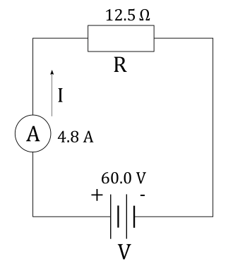
$$
I = 4.8 ~mathrm{A}
$$
$V= 4.5 ~mathrm{V}$ battery
, an ammeter that reads $I = 85 ~mathrm{mA}$
and a resistor $R$
all connected in series.
We must also indicate the positive terminal on the battery and choose a conventional direction of current $I$ through the circuit.
Reading on ammeter connected in series to the resistor $R$ is the same as current $I$ flowing through the resistor $R$.
From Ohm’s law we know that current $I$ flowing through resistor $R$ with voltage $V$ across it is equal to:
$$
begin{align*}
I &= dfrac{V}{R} \
tag{express $R$ from the equation above} \
R &= dfrac{V}{I} \
R &= dfrac{ 4.5 ~mathrm{V} }{ 85 ~mathrm{mA} }\
R &= 52.9 ~mathrm{Omega }
end{align*}
$$
We are given current $I$ flowing through the circuit. We that positive terminal of the battery is the one labelled with $+$ sign. We also know that battery can be indicated as two parallel lines, normal to the wires in the circuit, where one of the lines is longer than the other. The longer line is positive terminal of the battery, while the shorter line is negative terminal of the battery. Direction of the current is from positive to negative terminal of the battery. We can now draw the circuit diagram.
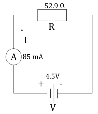
$$
R = 52.9 ~mathrm{Omega }
$$
Potential difference across the resistor is actually voltage across that resistor and to measure voltage across the resistor $R$ we connect voltmeter in parallel to resistor $R$. This way, since definition of parallel connection between two devices is that two devices are connected in parallel when voltage across them is the same, we conclude two things:
1) If we connect the voltmeter across the resistor $R$ in parallel, voltage across the voltmeter and across the resistor $R$ is the same.
2) Since voltmeter shows voltage $V_V$ across it and this voltage is same as voltage $V$ across the resistor $R$, we see that when we read the voltage $V_V$ on the voltmeter, we actually read voltage $V$ across the resistor.
In short, to measure the voltage across the resistors in problems $12$ and $13$ we simply connect the voltmeter in parallel to the resistor $R$.
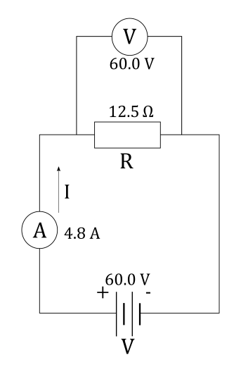
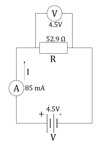
The circuit we are asked for looks like this:
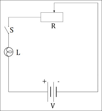

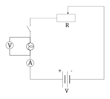
Since ammeter is used to measure the current $I$ through the lamp, we connect it in series with the lamp because definition of series connection states that two devices are connected in series if same current flows through both of them.
Since voltmeter is used to measure voltage $V$ across the lamp, we connect it in parallel to the lamp because definition of parallel connection states that two devices are connected in parallel if they are connected to the same voltage.
The resulting circuit looks like this: