
All Solutions
Page 631: Section Review
Power output on a resistors with resistance $R$, with current $I$ flowing through it and voltage $V$ across it can be expressed as:
$$
begin{align*}
P &= dfrac{V^2}{R} tag{1} \
end{align*}
$$
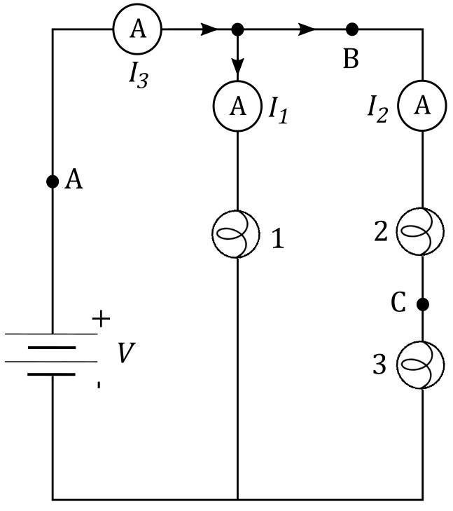
As we can see from the figure above, voltage across the lightbulb 1 is equal to voltage $V$ across the battery, since it’s connected in parallel to it. This means that power output $P_1$ on lightbulb 1 can be expressed as:
$$
P_1 = dfrac{V^2}{R}
$$
$$
V_2 + V_3 = V
$$
where $V_2$ is voltage across lightbulb 2 and $V_3$ is voltage across lightbulb 3. Since Ohm’s law states that voltage $V$ across a resistor with resistance $R$ and current $I$ flowing through is calculated as:
$$
V = I R
$$
we find that voltage $V_2$ is equal to:
$$
V_2 = I_2 R
$$
and voltage $V_3$ is equal to
$$
V_3 = I_2 R
$$
As we can see, voltages $V_2$ and $V_3$ are equal, which we can plug into the equation above:
$$
begin{align*}
V_2 + V_3 &= V \
tag{plug in $V_2 = I_2 R = V_3 $} \
V_2 + V_2 &= V\
2 V_2 &= V \
tag{express $V_2$ from the equation above} \
V_2 &= dfrac{V}{2}
end{align*}
$$
$$
begin{align*}
P_2 &= dfrac{V_2^2}{R} \
tag{plug in $V_2 = dfrac{V}{2} $ } \
P_2 &= dfrac{bigg(dfrac{V}{2} bigg)^2}{R} \
P_2 &= dfrac{V^2}{R} dfrac{1}{4} \
tag{plug in $ P_1 = dfrac{V^2}{R} $} \
P_2 &= dfrac{P_1}{4}
end{align*}
$$
Power output $P_3$ on lightbulb 3 is equal to:
$$
begin{align*}
P_3 &= dfrac{V_3^2}{R} \
tag{plug in $V_2 = V_3 $} \
P_3 &= dfrac{V_2^2}{R} \
tag{plug in $ P_2 = dfrac{V_2^2}{R} = dfrac{P_1}{4} $ } \
P_3 &= dfrac{P_1}{4}
end{align*}
$$
As we can see, power output $P_1$ on lightbulb 1 is equal to:
$$
boxed{ P_1 = dfrac{V^2}{R}}
$$
while power output on lightbulbs 2 and 3 are equal to:
$$
boxed{P_2 = P_3 = dfrac{P_1}{4} }
$$
boxed{P_2 = P_3 = dfrac{P_1}{4} }
$$
since (2) and (3) are connected in series so they have high total resistance thus resulting in lower electric current intensity than of Bulb (1)
$$I_3=I_1+I_2$$
$$I_2=I_3-I_1$$
$$I_2=1.7-1.1$$
Finally, the current $I_2$ is:
$$boxed{I_2=0.6,,rm{A}}$$
$$
I_3 = I_2 + I_1
$$
We’re told that current $I_3 = 1.7 ~mathrm{A}$ and current $I_1 = 1.1 ~mathrm{A}$. Now let’s use the equation above to express $I_2$:
$$
begin{align*}
I_3 &= I_2 + I_1 \
tag{express $I_2$ from the equation above }\
I_2 &= I_3 – I_1 \
tag{plug in the values} \
I_2 &= 1.7 ~mathrm{A} – 1.1 ~mathrm{A}
end{align*}
$$
$$
boxed{ I_2 = 0.6 ~mathrm{A} }
$$
I_2 = 0.6 ~mathrm{A}
$$
I_3 = I_1 + I_2
$$
I_2 = 0.6A
$$
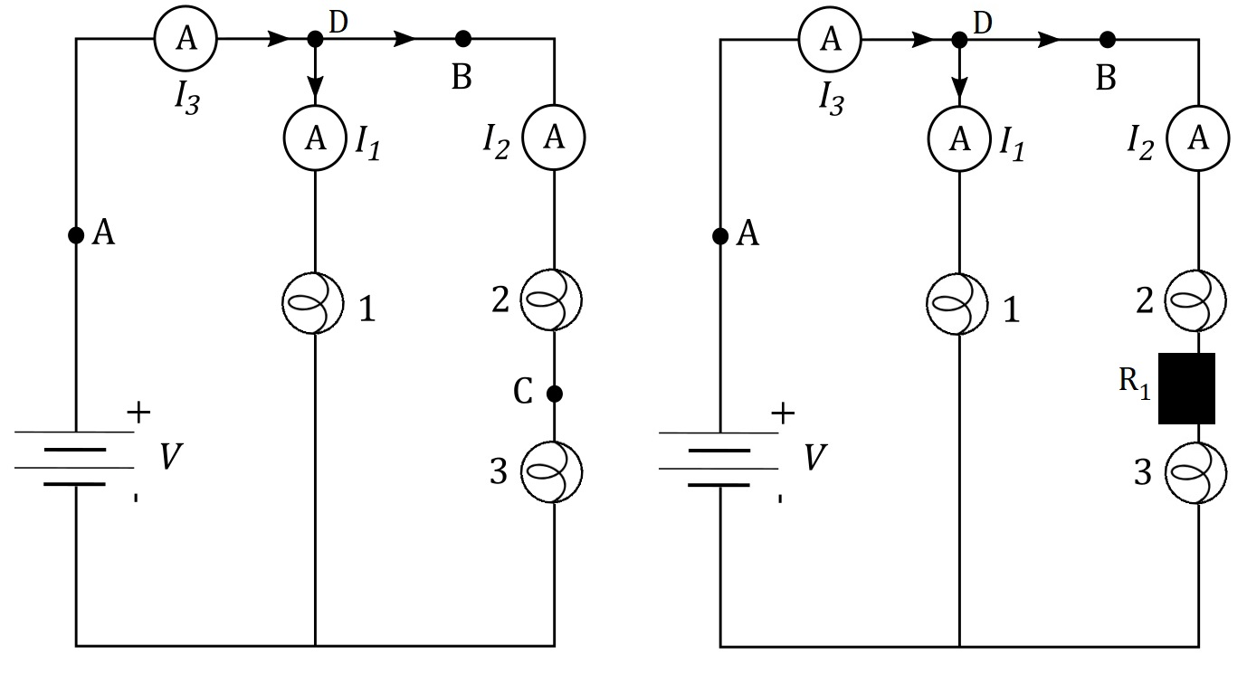
This means that if we compare the power output on the lightbulbs before and after the wire at point C broke, we’ll also compare brightness of the bulbs in the initial case when wire didn’t break and in the final case when it did.
Power output on a resistors with resistance $R$, with current $I$ flowing through it and voltage $V$ across it can be expressed as:
$$
begin{align*}
P &= dfrac{V^2}{R} tag{1} \
end{align*}
$$
If we take a look at lightbulbs 2 and 3, we’ll see that they are connected in series to one another, but their combination is connected in parallel to the battery. This means that:
$$
V_2 + V_3 = V
$$
where $V_2$ is voltage across lightbulb 2 and $V_3$ is voltage across lightbulb 3. Since Ohm’s law states that voltage $V$ across a resistor with resistance $R$ and current $I$ flowing through is calculated as:
$$
V = I R
$$
we find that voltage $V_2$ is equal to:
$$
V_2 = I_2 R
$$
and voltage $V_3$ is equal to
$$
V_3 = I_2 R
$$
As we can see, voltages $V_2$ and $V_3$ are equal, which we can plug into the equation above:
$$
begin{align*}
V_2 + V_3 &= V \
tag{plug in $V_2 = I_2 R = V_3 $} \
V_2 + V_2 &= V\
2 V_2 &= V \
tag{express $V_2$ from the equation above} \
V_2 &= dfrac{V}{2}
end{align*}
$$
$$
begin{align*}
P_{2i} &= dfrac{V_{2i}^2}{R} \
tag{plug in $V_{2i} = dfrac{V}{2} $ } \
P_{2i} &= dfrac{bigg(dfrac{V}{2} bigg)^2}{R} \
P_{2i} &= dfrac{V^2}{R} dfrac{1}{4}
end{align*}
$$
Power output $P_{3i}$ on lightbulb 3 is equal to:
$$
begin{align*}
P_{3i} &= dfrac{V_{3i}^2}{R} \
tag{plug in $V_{2i} = V_{3i} $} \
P_{3i} &= dfrac{V_{2i}^2}{R} \
tag{plug in $P_{2i} = P_{3i}$} \
P_{3i} &= dfrac{V^2}{R} dfrac{1}{4}
end{align*}
$$
As we can see, power output on both of the lightbulbs before the wire breaks is the same and equal to:
$$
boxed{ P_{2i} = P_{3i} = dfrac{V^2}{4R} }
$$
$$
begin{align*}
V = V_{2f} + V_{3f} + V_1 tag{2}
end{align*}
$$
where $V_{2f}$ and $V_{3f}$ is voltage across lightbulbs 2 and 3, respectively, and $V_1$ is voltage across the new resistor $R_1$. As stated above, since Ohm’s law states that voltage $V$ across a resistor with resistance $R$ and current $I$ flowing through is calculated as:
$$
V = I R
$$
we find that voltage $V_{2f}$ is equal to:
$$
V_{2f} = I_{2f} R
$$
and voltage $V_3$ is equal to
$$
V_{3f} = I_{2f} R
$$
where $R$ is resistance of the lightbulb and $I_{2f}$ is current flowing through this branch of the circuit when resistor $R_1$ is added. As we can see from the two equations above, voltages $V_{2f}$ and $V_{3f}$ are the same, which means that voltage across both of the lightbulbs is the same, which we can plug into equation $(2)$:
$$
begin{align*}
V &= V_{2f} + V_{3f} + V_1 \
V &= V_{2f} + V_{2f} + V_1 \
V &= 2 V_{2f} + V_1 \
tag{express $V_{2f}$ from the equation} \
2 V_{2f} &= V – V_1 \
V_{2f} &= dfrac{V – V_1}{2}
end{align*}
$$
$$
P = dfrac{V^2}{R}
$$
We see that since voltage across lightbulbs 2 and 3 is the same and they have the same resistance, power output will be the same on both of them.
$$
begin{align*}
P_{2f} &= dfrac{V_{2f} ^2}{R} \
tag{plug in $V_{2f} = dfrac{V – V_1}{2} $ }\
P_{2f} &= dfrac{ bigg(dfrac{V – V_1}{2} bigg)^2 }{R} \
tag{square the numerator in the equation above} \
P_{2f} &= dfrac{ dfrac{(V – V_1)^2}{4} }{R}
end{align*}
$$
As we can see, power output on lightbulbs 2 and 3 is the same after the wire breaks and gets replaced with a resistor $R_1$ and is equal to:
$$
boxed{ P_{2f} = P_{3f} = dfrac{(V – V_1)^2}{4R} }
$$
$$
begin{align*}
dfrac{ P_{2f} }{ P_{2i}} &= dfrac{ dfrac{(V – V_1)^2 }{4R} }{ dfrac{V^2}{4R} } \
tag{cancel out the $4R$} \
dfrac{ P_{2f} }{ P_{2i}} &= dfrac{(V – V_1)^2 }{V^2} \
tag{group the terms on the right side of the equation} \
dfrac{ P_{2f} }{ P_{2i}} &= left( dfrac{V- V_1}{V} right)^2\
dfrac{ P_{2f} }{ P_{2i}} &= left( 1- dfrac{V_1}{V} right)^2
end{align*}
$$
As we can see, the term on the right side of the equation above is lower than 1, which means:
$$
dfrac{ P_{2f} }{ P_{2i}} < 1
$$
$$
boxed{ P_{2f} < P_{2i} }
$$
Since power output on the lightbulbs decreased, their brightness also decreased.
$$
P_{2f} < P_{2i}
$$
$$epsilon =V$$
$$V=V_2+V_3$$
$$epsilon =V_2+V_3$$
$$epsilon =3.8+4.2$$
Finally:
$$boxed{epsilon =8,,rm{V}}$$
V_{total}=V_1 +V_2
$$
$$
V = V_2 + V_3 = 3.8 + 4.2 = 8.0 V
$$
8.0 V
$$
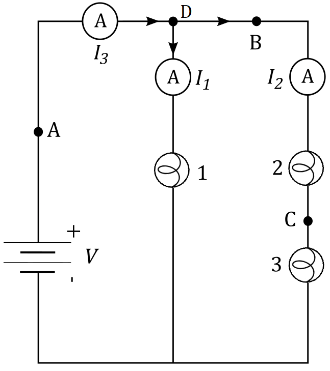
The bulbs are connected in series and have a voltage of $V_2=3.8,,rm{V}$ and $V_3=4.2,,rm{V}$
$$I_2=I_3$$
$$R=frac{V}{I}$$
$$frac{V_2}{I_2}=frac{V_3}{I_3}$$
Since currents are equal we can negate them:
$$V_2=V_3$$
Inserting values, we can see that ti is simply not true. Which also means that resistances are not equal:
$$boxed{R_2 neq R_3}$$
Which finally means that the bulbs are **not identical**.
Ohm’s law states that the current $I$ flowing through a resistor $R$ with voltage $V$ across it is given as:
$$
I = dfrac{V}{R}
$$
We can express resistance $R$ from the equation above:
$$
R = dfrac{V}{I}
$$
We see from the figure above that the same current $I_2$ flows through both of the lightbulbs. Let’s determine the resistance $R_2$ of lightbulbs 2
$$
begin{align*}
R_2 &= dfrac{V_2}{I_2}
end{align*}
$$
Resistance $R_3$ of lightbulb 3 is:
$$
begin{align*}
R_3 &= dfrac{V_3}{I_2}
end{align*}
$$
In order for these lightbulbs to be identical, they need to have the same resistance, which means that $R_2 = R_3$. Let’s see if this holds:
$$
begin{align*}
R_2 &= R_3 \
tag{plug in $R_3 = dfrac{V_3}{I_2} $ and $ R_2 = dfrac{V_2}{I_2}$ }\
dfrac{V_2}{I_2} &= dfrac{V_3}{I_2} \
tag{cancel out $I_2$} \
V_2 &= V_3
end{align*}
$$
We see that in order for these lightbulbs to be identical, they need to have the same resistance, which would be true in this case if voltage across both of them was the same. However, since $V_2 = 3.8 ~mathrm{V}$ and $V_3 = 4.2 ~mathrm{V}$, we conclude that these lightbulbs are not identical.
V_2 = 3.8
$$
and
$$
V_3 = 3.6
$$
2)circuit breakers
3) Ground fault circuit interrupters
$$
begin{align*}
P &= I V tag{1} \
P &= I^2 R tag{2} \
P &= dfrac{V^2}{R} tag{3} \
end{align*}
$$
Note that in the figure above we aren’t given voltage $V$ across the battery, nor the currents $I_3$, $I_2$ and $I_3$. We also aren’t given resistance $R_1$,$R_2$ and $R_3$
on bulbs 1,2 and 3 respectively, which means that we have all the freedom to make the power outputs $P_1$, $P_2$ and $P_3$ on the three bulbs the same. In other words, we have a following condition:
$$
P_1 = P_2 = P_3
$$
where $P_1$, $P_3$ and $P_3$ are power outputs on bulbs 1,2 and 3 respectively. Let’s try to satisfy the condition above using equation $(1)$.
$$
P_1 = I_1 V_1
$$
where $I_1$ is current flowing through bulb 1 and $V_1$ is voltage across it. We see that this voltage is equal to voltage across the battery, since this bulb is connected in parallel to the battery $V$, which means:
$$
P_1 = I_1 V
$$
We see that bulbs 2 and 3 are connected in series, which means that the same current $I_2$ flows through both of them.
Power output $P_2$ on bulb 2 is given as:
$$
P_2 = I_2 V_2
$$
while power output $P_3$ on bulb 3 is given as:
$$
P_3= I_2 V_3
$$
We see that in order for power outputs $P_2$ and $P_3$ to be equal we have:
$$
begin{align*}
P_3 &= P_2 \
tag{plug in $P_2 = I_2 V_2$ and $P_3= I_2 V_3$ } \
I_2 V_2 &= I_2 V_3 \
tag{cancel out $I_2$} \
V_2 &= V_3
end{align*}
$$
but since this would change the whole schematic of circuit, this solution is not viable. We know that Ohm’s law states that voltage $V$ across a resistor $R$ with current $I$ flowing through it is calculated as:
$$
V = IR
$$
From the equation above we see that if the same current $I$ flows through multiple resistors with the same resistance $R$, same voltage $V$ will be applied across all the resistors. In our case, this means that if resistance $R_2$ of bulb 2 and resistance $R_3$ of bulb 3 is the same $R_2 = R_3$, these bulbs would have the same voltage across them:
$$
begin{align*}
V_2 &= I_2 R_2 \
V_3 &= I_2 R_3
end{align*}
$$
As said, since $P_1 = P_2 = P_3$, we have:
$$
begin{align*}
P_1 &= P_2
tag{plug in $P_1 = I_1 V_1$ and $P_2 = I_2 V_2$} \
I_1 V_1 &= I_2 V_2 \
tag{plug in $V_1 = V$} \
I_1 V &= I_2 V_2 \
tag{express $I_1$ from the equation above} \
I_1 &= dfrac{ I_2 }{V} V_2 tag{4}
end{align*}
$$
$$
begin{align*}
V_2 + V_3 &= V \
tag{plug in $V_2 = V_3$} \
V_2 + V_2 &= V \
V_2 cdot 2 &= V \
tag{express $V_2$} \
V_2 &= dfrac{V}{2} tag{5}
end{align*}
$$
We can plug this result for $V_2$ into the equation $(4)$:
$$
begin{align*}
I_1 &= dfrac{I_2 }{V} V_2 \
I_1 &= dfrac{ I_2 }{V} dfrac{V }{2} \
tag{cancel out $V$} \
I_1 &= dfrac{I_2}{2} tag{6}
end{align*}
$$
As we can see, the first solution is to have the same voltage $V_2$ and $V_3$ across bulbs 2 and 3 by having the same resistance $R_2 = R_3$ on these two bulbs, while the current $I_1$ flowing through bulb 1 is calculated as stated above, which means:
$$
boxed{
text{ 1st solution:}~~ R_2 = R_3 ~~ text{and}~~ I_1 = dfrac{I_2 }{2} }
$$
$$
P = I^2 R
$$
This means that in order for the two bulbs to have the same power output, we have:
$$
begin{align*}
P_2 &= P_3 \
tag{apply the equation above to $P_2$ and $P_3$} \
tag{ current $I_2$ flows through bulbs 2 and 3} \
I_2^2 R_2 &= I_2^2 R_3 \
tag{cancel out $I_2^2$} \
R_2 &= R_3
end{align*}
$$
As expected, as in the first solution, we found that in order for the two bulbs connected in series to have the same power output, their resistance must be the same. Now let’s compare the power output $P_1$ on bulb 1 with power output $P_2$ on bulb 2:
$$
begin{align*}
P_1 &= P_2 \
tag{apply the equation $(1)$ to $P_2$ and $P_1$} \
I_1^2 R_1 &= I_2^2 R_2 \
tag{plug in $ I_1 = dfrac{I_2 }{2} $ from equation $(6)$} \
left( dfrac{I_2 }{2} right)^2 R_1 &= I_2^2 R_2 \
dfrac{I_2^2 }{4 } R_1 &= I_2^2 R_2 \
tag{cancel out $I_2^2$} \
dfrac{R_1}{4} &= R_2 \
tag{express $R_1$ from the equation above } \
R_1 &= 4 R_2
end{align*}
$$
As we can see , second solution that satisfies the condition $P_1 = P_2 = P_3$ is to have bulbs 2 and 3 have the same resistance $R_2 = R_3$ while this resistance is 4 times greater than resistance $R_1$ on bulb 1, stated as:
$$
boxed{
text{ 2nd solution:}~~ R_1 = 4 R_2 = 4 R_3 }
$$
$$
P = dfrac{V^2}{R}
$$
We can apply this equation to $P_1$, $P_2$ and $P_3$ to have:
$$
begin{align*}
P_1 &= dfrac{V^2}{R_1} \
P_2 &= dfrac{V_2^2}{R_2} \
P_3 &= dfrac{V_3^2}{R_3}
end{align*}
$$
Let’s compare the power outputs $P_2$ and $P_3$:
$$
begin{align*}
P_2 &= P_3 \
dfrac{V_2^2}{R_2} &= dfrac{V_3^2}{R_3} \
tag{note that $V_2 + V_3 = V$} \
dfrac{V_2^2}{R_2} &= dfrac{(V – V_2) ^2}{R_3} \
tag{find square root of the equation} \
dfrac{V_2}{sqrt{R_2}} &= dfrac{V -V_2}{sqrt{R_3}} \
tag{rewrite the term on the right side as} \
dfrac{V_2}{sqrt{R_2}} &= dfrac{V}{sqrt{R_3}} – dfrac{V_2}{sqrt{R_3}} \
dfrac{V_2}{sqrt{R_2}} + dfrac{V_2}{sqrt{R_3}} &= dfrac{V}{sqrt{R_3}} \
tag{group the terms on the left side of the equation} \
V_2 left( dfrac{1}{sqrt{R_2}} + dfrac{1}{sqrt{R_3}} right) &= dfrac{V}{sqrt{R_3}} \
%
%
V_2 left( dfrac{sqrt{R_2} + sqrt{R_3}}{sqrt{R_2 R_3}} right) &= dfrac{V}{sqrt{R_3 }} \
tag{cancel out $sqrt{R_3}$} \
V_2 left( dfrac{sqrt{R_2} + sqrt{R_3}}{sqrt{R_2 }} right) &= V \
V_2 left( 1 + sqrt{dfrac{R_3}{R_2}} right) &= V tag{7} \
V_2 + V_2 cdot sqrt{dfrac{R_3}{R_2}} &= V \
tag{compare with $V_2 + V_3 = V$} \
V_3 &= V_2 cdot sqrt{dfrac{R_3}{R_2}} tag{8}
end{align*}
$$
$$
V_2 = I_2 R_2
$$
while voltage $V_3$ across bulb 3 will be equal to:
$$
V_3 = I_2 R_3
$$
We can plug this into equation $(8)$:
$$
begin{align*}
V_3 &= V_2 cdot sqrt{dfrac{R_3}{R_2}} \
I_2 R_3 &= I_2 R_2 sqrt{dfrac{R_3}{R_2}} \
tag{cancel out $I_2$} \
R_3 &= R_2 sqrt{dfrac{R_3}{R_2}} \
tag{square the equation} \
R_3^2 &= R_2^2 dfrac{R_3}{R_2}
tag{cancel out $R_3$ and $R_2$} \
R_3 &= R_2
end{align*}
$$
$$
begin{align*}
V_3 &= V_2 sqrt{dfrac{R_3}{R_2}} \
tag{plug in $R_2 = R_3 $ } \
V_3 &= V_2 cdot 1
end{align*}
$$
Going back to equation $(7)$ we have:
$$
begin{align*}
V_2 left( 1 + sqrt{dfrac{R_3}{R_2}} right) &= V \
tag{plug in $R_2 = R_3 $ } \
V_2 (1+ 1) &= V \
V_2 cdot 2 &= V \
V_2 &= dfrac{V}{2} = V_3
end{align*}
$$
This means that thirds solution is to have the same resistance $R_2$ and $R_3$ on bulbs 2 and 3, while voltage across them is equal $V_2 = V_3$. This voltage is also equal to half the voltage across the battery, which means:
As we can see, the first solution is to have the same voltage $V_2$ and $V_3$ across bulbs 2 and 3 by having the same resistance $R_2 = R_3$ on these two bulbs, while the current $I_1$ flowing through bulb 1 is calculated as stated above, which means:
$$
boxed{
text{ 3rd solution:}~~ R_2 = R_3 ~~ text{and}~~ V_2 = dfrac{V }{2} }
$$
$$
boxed{ R_2 = R_3 = dfrac{R_1}{4} ~~ text{and}~~ I_1 = dfrac{I_2}{2} ~~ text{and}~~ V_2 = dfrac{V}{2} }
$$
R_2 = R_3 = dfrac{R_1}{4} ~~ text{and}~~ I_1 = dfrac{I_2}{2} ~~ text{and}~~ V_2 = dfrac{V}{2}
$$
