Physics: Principles and Problems
9th Edition
Elliott, Haase, Harper, Herzog, Margaret Zorn, Nelson, Schuler, Zitzewitz
ISBN: 9780078458132
Textbook solutions

All Solutions

Page 664: Assessment

Exercise 32
Step 1
1 of 2
Exercise scan
Result
2 of 2
The magnitude of the force on a current-carrying wire is given by $F=ILB$.

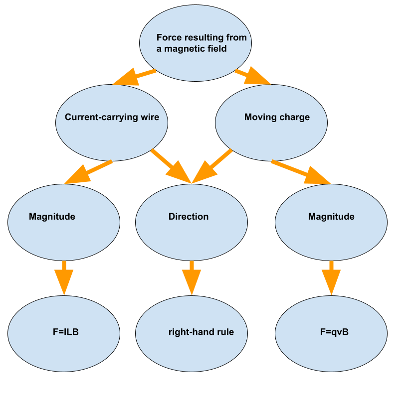
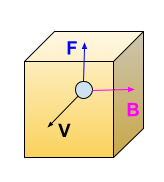
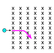
The magnitude of the force on a moving charge is given by $F=qvB$.

The direction of the force is in both cases obtained via right-hand rule.

Exercise 33
Solution 1
Solution 2
Step 1
1 of 4
In this problem we need to state the rule for magnetic attraction and repulsion.
Step 2
2 of 4
If you hold two bar magnets, and bring one close to the other, you will observe one of two things.
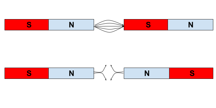
Either the magnets will resist being pushed together, or they will snap together.
Step 3
3 of 4
When two **opposite** magnetic poles are close, they attract each other. When **like** poles are pushed together, there is a force of repulsion.
Step 4
4 of 4
The rule for magnets is that like poles **repel** and unlike poles **attract**.
Step 1
1 of 2
The same poles will repel each other whereas the opposite poles will attract each other.
Result
2 of 2
Same poles repeal and opposite poles attract each other.
Exercise 34
Solution 1
Solution 2
Step 1
1 of 4
In this problem we need to discuss differences between temporary and a permanent magnet.
Step 2
2 of 4
A permanent magnets retain its magnetic properties for a **long periods** of time. Examples of such magnets would be iron, nickel, cobalt and some rare earth alloys.
Step 3
3 of 4
Temporary magnets act like permanent magnets when they are within a strong magnetic field. When the magnetic field disappears. they **lose their magnetism**.
Step 4
4 of 4
So the main difference is that permanent magnets keep their properties regardless of the **magnetic field** surrounding and for a much **longer time** than temporary magnets.
Step 1
1 of 2
A temporary magnet is a magnet which magnetic properties decrease with time. On the other hand the properties of a permanent magnet can be considered constant.
Result
2 of 2
Temporary magnets loose their magnetism over time and permanent do not.
Exercise 35
Solution 1
Solution 2
Step 1
1 of 2
In this problem we need to name three common magnetic elements.
Step 2
2 of 2
What we consider magnetic materials are usually ferromagnetic materials; they are attracted to a magnet strongly enough that the attraction can be felt. These materials are the only ones that can retain magnetization and become magnets.
Main elements from this group are **iron, nickel and cobalt** and their alloys.
Step 1
1 of 2
– Iron

– Nickle

-Cobalt

Result
2 of 2
Iron, Nickle, Cobalt
Exercise 36
Step 1
1 of 2
Exercise scan
Result
2 of 2
The lines go from the North to the South magnetic pole by convention.
Exercise 37
Step 1
1 of 2
Exercise scan
Result
2 of 2
When two opposite poles are close to each other field lines go from North to South. When the same poles are close to each other field lines deflect from each other.
Exercise 38
Solution 1
Solution 2
Step 1
1 of 2
We need to discuss what would happen if we broke a magnet in two pieces, and whether or not would we end up with two isolated north and south poles.
Step 2
2 of 2
Magnet can be seen as a group of smaller magnets that are in contact with each other. Each one has a small north and south pole and reinforces the equal magnetic fields in the others.
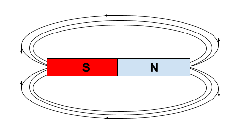
If one is cut in half, the new endings faces will become the new north or south poles of the smaller pieces.
Therefore, **no, we will not end up with a separate N and S poles**.
Step 1
1 of 2
No, because the magnetic poles are just the physical ends of the alignment of microscopic magnetic moments. Once the magnet is broken, the south/north pole will be opposite ends of the remaining poles. So far magnetic monopoles were not detected.
Result
2 of 2
No, we wouldn’t.
Exercise 39
Solution 1
Solution 2
Step 1
1 of 5
In this problem we need to describe the application of the first right-hand rule to determine the direction of a magnetic field around a straight conducting wire.
Step 2
2 of 5
In order to solve this problem we need to first find the direction of the current flow in the wire.
Step 3
3 of 5
Next, we are going to press the thumb of the right hand in the direction of the current.
Step 4
4 of 5
Next step is wrapping the remaining finger of the right hand around the wire.
Step 5
5 of 5
The fingers now point in the direction of the **magnetic field lines**. The lines are in circular motion and the fingers will point in the correct direction.
Step 1
1 of 2
In order to apply the first right-hand rule to determine the direction of the magnetic field around a straight current-carrying wire we take our right fist and we are going to make a thumb up gesture with our right-hand thumb . Then we are goin to align that thumb with the wire in the direction of the current flow. Now we take and grab the wire and our remaining four fingers will now coincide with the magnetic field lines.
Result
2 of 2
We “grab” the wire with our right hand and our thumb along the current direction. Then our fingers mimic the magnetic field lines.
Exercise 40
Solution 1
Solution 2
Step 1
1 of 3
We need to discuss why is the magnetic field inside of the loop of the current carrying wire stronger than the one on the outside.
Step 2
2 of 3
In order to solve this problem we need to take a look at the equation for the magnetic field of a current carrying wire bent in a loop:
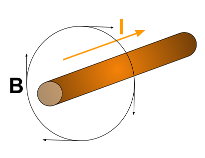
$$B=frac{mu_0 I}{2R}$$
From this equation it can be concluded that the larger the distance $R$, the weaker the field.
Step 3
3 of 3
The other explanation however can be found in a way the field is calculated.
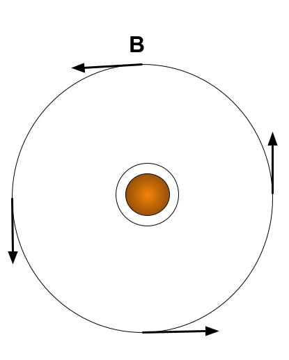
It is a result of a sum of magnetic fields produced by smaller segments of a wire.
Since the inner parts are closer, the magnetic fields of the wire are **closer** and therefore there is a lot more overlap, making thus a stronger magnetic field than it is on the outer parts of the loop.
Step 1
1 of 2
The reason for this is the fact that the each segment of the loop will have the force adding up inside the loop with other segments regardless of the position. On the other hand outside the loop some segments will produce fields that oppose to each other thus reducing the field strength. Of course if we move far enough, the field will start to decline regardless.
Result
2 of 2
The field inside the loop is the superposition of field lines of each segment of the loop whereas outside the loop, some segments can reduce each others fields.
Exercise 41
Solution 1
Solution 2
Step 1
1 of 3
In this problem we need to explain the application of the second right-hand rule to determine the polarity of a magnet.
Step 2
2 of 3
Right-hand rule is a mnemonic technique used to help determine the **direction** of electromagnetic forces.
The second right-hand rule helps us determine the magnetic field made by a current in a straight wire **curls** around the wire in a ring.
Step 3
3 of 3
The second right-hand rule states that if the fingers of a right hand curl in the direction of the current in the coil, the **thumb** points in the direction of the North pole.
Step 1
1 of 2
The second right-hand rule is used to determine the polarity of an electromagnet in the following way: we grab the coil with our right hand so that our fingers coincide with the current direction inside the coil. Then, our elongated thumb shows the North pole of the electromagnet.
Result
2 of 2
When we grab a coil with our fingers following the current direction our thumb points to the North pole of an electromagnet.
Exercise 42
Solution 1
Solution 2
Step 1
1 of 2
We need to discuss how is it possible that each electron in a piece of iron acts like a tiny magnet, but the whole piece does not.
Step 2
2 of 2
Larger piece of iron consists of a large number of smaller pieces and those pieces can act as a smaller magnet.
Magnetic property of material is a **macroscopic property** in which all smaller pieces are alligned in a way to create a difference in charge between two sides.
This means that microscopically one piece can act as a magnet, but if macroscopically all those pieces are **not alligned** in a way needed to create a larger magnet, the large piece will **not be a magnet**.
Step 1
1 of 2
The magnetism, as we know it is a macroscopic property which assumes the collective alignment of microscopic magnetic moments. In iron these moments can and can be not aligned in a way that will create macroscopic magnetic effects. This depends on many factors such as presence of external fields, temperature etc.
Result
2 of 2
The iron needs a collective alignment of the electronic magnetic moments to start displaying magnetism.
Exercise 43
Solution 1
Solution 2
Step 1
1 of 3
We need to discuss the effects of dropping or heating a magnet.
Step 2
2 of 3
In order to solve this problem we need to understand what is magnetism and what causes it.
Magnetism is a macroscopic property of material. It is caused by a correctly alligned smaller particles in a way that one side of the material has different charge than the other. All in all it is relatively structured configuration.
Step 3
3 of 3
Dropping or heating a material has an effect of increasing the internal energy and therefore **increasing entropy** of material. Since entropy is known as chaos, which is opposite of order and **structured configuration** needed for magnetism to exist, increase in entropy wil result in **decrease in magnetic strength**.
Step 1
1 of 2
Dropping and heating will affect the internal energy of the magnet and since the internal energy will increase, the entropy is likely to increase and having the magnetic moment aligned is an entropically non-favorable configuration.
Result
2 of 2
Because both events will break or damage the existing alignment of the microscopic magnetic moments.
Exercise 44
Solution 1
Solution 2
Step 1
1 of 3
In this problem we need to explain the application of the third right-hand rule in order to determine the direction of force on a conducting wire placed in a magnetic field.
Step 2
2 of 3
In order to solve this problem we first need to understand what is third right-hand rule and why is it used.
Right-hand rules are a technique used for easier determining the direction of electromagnetic forces.
Step 3
3 of 3
Third right-hand rule can be used in a way that we point **index finger** in the direction the current is flowing, **middle finger** in the direction of the magnetic field, and **thumb** in the direction of the **force** on the wire.
Step 1
1 of 2
We use the third right-hand rule as follows: we point our fingers in the direction of the field, our thumb in the direction of the current and our palm is showing the direction of the force on the wire.
Result
2 of 2
Current-thumb

Field-fingers

Force-palm

Exercise 45
Solution 1
Solution 2
Step 1
1 of 3
We need to discuss whether the fact that there is no force acting on a conducting wire means that there is no magnetic field present.
Step 2
2 of 3
In order to solve this problem we need to take a look at the equation describing the force on the conducting wire in a magnetic field:
$$F=ILBsin (theta)$$
Step 3
3 of 3
From the previous equation we can see that even if we have $I$, $L$ and $B$ the force can still be zero.
If the $sin (theta) =0$ the force will be zero even with magnetic field present. This is possible if the magnetic field and the wire are co-linear.
So, **no, we cannot conclude that there is no magnetic field**.
Step 1
1 of 2
No, we cannot because the force is the cross product of the direction of the current and the magnetic field so if this two are co-linear we will detect no force whatsoever.
Result
2 of 2
No, we can not.
Exercise 46
Solution 1
Solution 2
Step 1
1 of 4
We need to discuss what device is created by adding a shunt to the galvanometer.
Step 2
2 of 4
In order to solve this problem, we first must understand the working principle of galvanometer:
A galvanometer is an electromechanical measuring instrument for electric current. It works by deflecting a pointer in response to an electric current flowing through a coil in a constant magnetic field.
Step 3
3 of 4
We also need to understand what is the shunt. It is a device that creates a low-resistance path for electric current, to allow it to pass around another point in the circuit
Step 4
4 of 4
Combined we get the description very simmilar to the ammeter, which means that by adding shunt to the galvanometer, **we will get ammeter**.
Step 1
1 of 2
As shown in Figure 24-19, if we add a shunt to a galvanometer we are going to obtain a device called ammeter.
Result
2 of 2
We obtain an ammeter.
Exercise 47
Solution 1
Solution 2
Step 1
1 of 3
We need to think of a way to determine a north and south pole of a magnet by using a tennis ball with a bar magnet fixed inside.
Step 2
2 of 3
If we understand the interaction between Earth’s magnetic field and a compass, we can see that we can create a compass out of that tennis ball.
By simply putting it in the water, the ball will orientate in such a way to fit the effects of the Earth’s magnetic field, thus becoming a compass.
Step 3
3 of 3
Since **opposite** poles attract, the south pole of the magnet bar will point towards Earth’s north and magnet’s north will point into Earth’s south.
Step 1
1 of 2
The magnetic poles of this hidden magnet can be found with a compass. If we assume that the magnet is strong enough that in its vicinity of the compass the Earth’s magnetic field is going to be neglectable, the needle of the compas once we put it on the ball will point towards the south magnetic pole of the bar (not north which is a common misconception, the Earth’s north geographic pole is its south magnetic pole and vice versa). Now we will glide along the ball’s surface until the compass starts rotating freely. That means that we have located the south magnetic pole and the north magnetic pole is on the opposite side.
Result
2 of 2
For such an experiment we can use the compass.
Exercise 48
Solution 1
Solution 2
Step 1
1 of 3
We need to think of a way to determine whether a piece of metal that is attracted to one pole of a large magnet is permanent or temporary magnet.
Step 2
2 of 3
In order to solve this problem we need to be aware of the fact that the like poles repel and opposite magnetic poles attract.
Step 3
3 of 3
Since the piece of metal is attracted to one side of the large magnet, we can see if it is permanent magnet if we simply turn the piece of metal around.
If it **is permanent magnet**, now the like poles will be facing each other and the magnets will **repel**.
If they still **attract**, the piece of metal is not permanent but rather **temporary magnet**.
Step 1
1 of 2
To check weather a piece of metal is a permanent or temporary magnet we can first mark the end attracted to the magnet. Now, we can take the piece of metal and drop it several times to the ground. Now, we should take the opposite end of the metal piece in see is it attracted the the same part of the large magnet. If yes, then it is a temporary magnet if no that is a permanent magnet.
Result
2 of 2
By dropping the metal piece to the ground we can loose it’s magnetization and than the opposite pole should be attracted to same pole of the large magnet in the case of the temporary magnet. If they repel, the magnet is a permanent one.
Exercise 49
Step 1
1 of 2
The Newton’s third law says that the force of action equals the force of reaction therefore the two forces have to be the same. We do not see the Earth moving because the force is very small.
Result
2 of 2
The force is the same between the two.
Exercise 50
Step 1
1 of 2
In order to cope with this unpleasant situation, we should remove the battery from the flashlight. Now, we will take the compass and wrap it with a wire this creating a sort of coil. One end of the wire we are going to attach to the battery and the second to the light. When we switch on the light, the current will create a magnetic field and the needle should point to the battery, i.e to the south magnetic pole.
Result
2 of 2
We should create a coil which will generate a uniform magnetic field.
Exercise 51
Step 1
1 of 2
In both cases the cause for the attraction is a polarization. In the case of magnets, there is a polarization due to the collective alignment of the microscopic magnetic moments whereas in case of the charged rod there is a polarization caused by physical separation of microscopic charges.
Result
2 of 2
In both cases a polarization occurs in the case of metal, magnetic and in the case of the rod, electrostatic.
Exercise 52
Step 1
1 of 2
1) We can bring a compass and put it above the wire. Based on the direction at which the needle points to we will be able to determine the direction of the current as from the first right-hand rule.

2) We could attach a dynamometer to the wire and bring a strong magnet were close to it. Based on which side the force acts on the wire, we can get the direction of the current as from the third right hand rule.

Result
2 of 2
1) Compass

2) Dynamometer

Exercise 53
Step 1
1 of 2
Due to the fact that the magnetic force acting on the wire is defined as

$$
F=ILBsintheta
$$

if we run the current along the magnetic field lines, i.e. in parallel with the magnetic field the force will be zero.

Result
2 of 2
The force will be zero when the current is parallel with the magnetic field.
Exercise 54
Step 1
1 of 3
In order to solve this problem, we are going to use the right-hand rule and the formula for the magnetic field of a straight current carrying wire

$$
B=frac{mu_0I}{2pi r}
$$

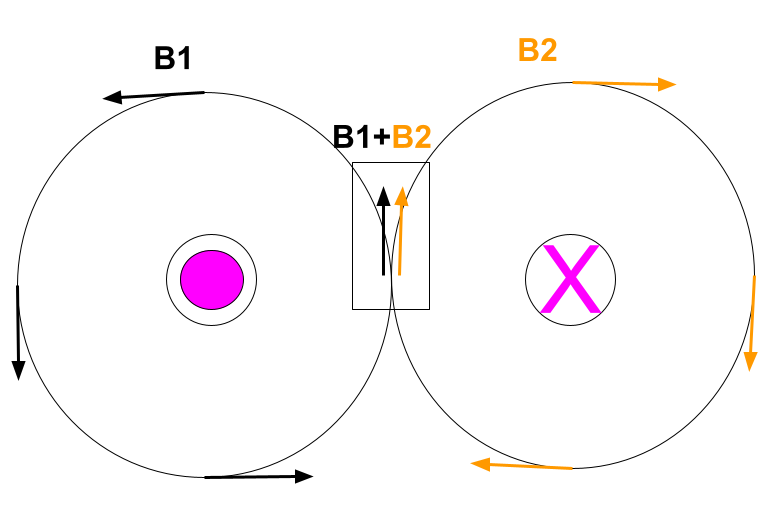
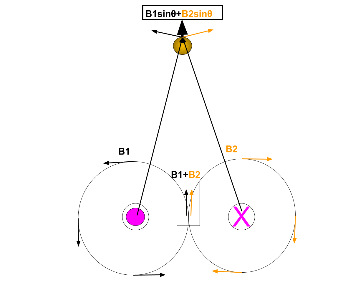
a) If the currents are in opposite directions the current will be larger in the space between the currents. We see this from the right-hand rule and it is show in the picture.

Exercise scan

Step 2
2 of 3
b) To see where the field of the opposite direction, parallel currents is twice the magnitude of the single one we will use the aforementioned formula. Let’s have that the distance between the currents is $d$ and since the field is only stronger between the wires we can write that at a point $r$ from the first wire we have the field

$$
B=B_1+B_2
$$

With the condition

$$
B=2B_1
$$

That implies that

$$
B_1=B_2
$$

$$
frac{mu_0I}{2pi r}=frac{mu_0I}{2pi (d-r)}
$$

$$
frac{1}{ r}=frac{1}{(d-r)}
$$

so finally we have that

$$
r=d-r
$$

$$
boxed{r=frac{d}{2}}
$$

So the field is twice as strong exactly at the middle plane between the wires.

c) The same logic can be repeated for the case when the currents are flowing in the same direction.
Then, we have that between the wires, the field is smaller and it is going to be zero only when

$$
B_1-B_2=0
$$

$$
B_1=B_2
$$

or

$$
boxed{r=frac{d}{2}}
$$

Result
3 of 3
a) The field is larger between the wires.

b) $r=frac{d}{2}$

c) $r=frac{d}{2}$

Exercise 55
Step 1
1 of 2
If we increase the resistance according to the Ohm’s law

$$
V=IR
$$

The range of the voltages will move towards higher voltages although it will still cover the same spectrum size it will have an offset.

Result
2 of 2
It will have an offset towards higher voltages.
Exercise 56
Step 1
1 of 2
No, it will not change the kinetic energy since there is no change in the speed (be careful, the speed is not equal to the velocity). This can be proven also mathematically. We have that
$vec F=qvec vtimes vec B$
However, we know that

$$
vec F =frac{dvec p}{dt}
$$

So we can write

$$
frac{dvec p}{dt}=qvec vtimes vec B
$$

Now, we can dot-multiply the equation with $vec p$ to get

$$
vec pcdot frac{dvec p}{dt}=qvec pcdot vec vtimes vec B
$$

But we know that $vec p=mvec v$ so the right side is identically zero and we have that

$$
frac{d}{dt}frac{p^2}{2m}=frac{dE_K}{dt}=0
$$

i.e. the kinetic energy is constant over time.

Result
2 of 2
The kinetic energy is constant over time.
Exercise 57
Step 1
1 of 2
If we are standing in front of the front wall and we are facing the back wall by the right hand rule, we see that the magnetic field is pointing to the right.Exercise scan
Result
2 of 2
To the right.
Exercise 58
Step 1
1 of 2
The magnitude of the magnetic field can be imagined as the density of the magnetic field lines. Since these lines are most dense at poles, the magnetic field is the strongest at the poles.
Result
2 of 2
The magnetic field is strongest at poles.
Exercise 59
Step 1
1 of 2
Since the same poles repel each other we are initially going to see some deflection, i.e. the suspended magnet will move to the left. This will happen until the gravitational force over powers the repulsive magnetic force and the system will from this metastable state go to the state where the magnets’ opposite poles face each other.
Result
2 of 2
The suspended magnet will first translate to the left and then rotate to meet the non-suspended magnet with its opposite pole.
Exercise 60
Step 1
1 of 2
Since the opposite magnetic poles attract, we are going to see the suspended magnet moving to the right.
Result
2 of 2
The suspended magnet will move to the right.
Exercise 61
Step 1
1 of 2
a)

2 and 4

(The poles are at the ends of a magnet.)

b)

2

(Magnetic field lines exit from the north pole)

c)

4

(Magnetic field lines enter its south pole)

Result
2 of 2
a) 2 and 4

b) 2

c) 4

Exercise 62
Step 1
1 of 2
In a close presence of a magnet strong enough the compass will align with the field lines with the north pointing towards the south pole. Therefore the south pole of the magnet in the figure 24-27 is at the right end.
Result
2 of 2
South pole is at the right end.
Exercise 63
Step 1
1 of 2
In order to solve this problem we are going to use the formula that defines the force acting on the current-carrying conductor by a magnetic field

$$
F=ILB
$$

From it we can express the magnetic field strength as

$$
B=frac{F}{IL}
$$

If we now plug in the values we obtain the following

$$
B=frac{0.6}{10times 1.5}
$$

Finally

$$
boxed{B=0.04textrm{ T}}
$$

Result
2 of 2
$$
B=0.04textrm{ T}
$$
Exercise 64
Step 1
1 of 2
To solve this problem we are going to use the right-hand rule. We have that the field is :Exercise scan
Result
2 of 2
The field is shown in the picture and it has a clockwise direction since the current is into the page. .
Exercise 65
Step 1
1 of 2
By using the right-hand rule we have that:Exercise scan
Result
2 of 2
The magnetic field lines are given in the picture and for the wire coming out of the page they are counterclockwise.
Exercise 66
Solution 1
Solution 2
Step 1
1 of 2
a)

The direction of the magnetic field inside the loop is into the page.

b)

The direction of the magnetic field outside the loop is out of the page.

Result
2 of 2
a) into the page

b) out of the page

Step 1
1 of 3
**a)** The direction of the magnetic field inside the loop can be determined using the right-hand rule. We curl the fingers in the current direction, and the thumb then points in the direction of the magnetic field. It is best seen in the picture below.

![‘slader’](https://slader-solution-uploads.s3.amazonaws.com/59dfdb71-6ec2-4915-aec3-0003272e47d5-1650649243238667.png)

Step 2
2 of 3
**b)** Outside the coil, the field goes in the opposite direction, following the rule that the magnetic field lines are going from the north to the west as pictured below.

![‘slader’](https://slader-solution-uploads.s3.amazonaws.com/4e55e8cf-6e1e-4687-b885-91a1529bbd31-1650649250778634.png)

Result
3 of 3
$$begin{align*}
&text{a) See the explanation.} \
&text{b) See the explanation.}
end{align*}$$
Exercise 67
Step 1
1 of 2
If we use any data-plotting software we obtain the curve shown in blue. On the other hand $frac{1}{r^2}$ function is given in red. So the answer to the question b) is no, the force doesn’t follow the inverse square law.

Exercise scan

Result
2 of 2
b) It doesn’t follow the inverse square low well.
Exercise 68
Step 1
1 of 2
Adding a shunt resistance in parallel to a galvanometer makes an ammeter.
Result
2 of 2
It is an ammeter.
Exercise 69
Step 1
1 of 2
The resistor in an ammeter is called a shunt.
Result
2 of 2
It is called a shunt.
Exercise 70
Step 1
1 of 2
When added in series to a galvanometer additional resistor makes a device called voltmeter used for measuring the potential differences.
Result
2 of 2
It is a voltmeter.
Exercise 71
Step 1
1 of 2
The resistance that turns a galvanometer into a voltmeter is called a multiplier.
Result
2 of 2
It is a multiplier.
Exercise 72
Step 1
1 of 2
By using the third right-hand rule we have that since the magnetic field is from the north to the south and that current is into the page the force is acting downwards onto the wire.
Result
2 of 2
Downwards.
Exercise 73
Step 1
1 of 2
In order to solve this problem we are going to use the formula that defines the force acting on the current-carrying conductor by a magnetic field

$$
F=ILB
$$

From it we can express the magnetic field strength as

$$
B=frac{F}{IL}
$$

If we now plug in the values we obtain the following

$$
B=frac{0.4}{8times 0.5}
$$

Finally

$$
boxed{B=0.1textrm{ T}}
$$

Result
2 of 2
$$
B=0.1textrm{ T}
$$
Exercise 74
Step 1
1 of 2
In order to solve this problem we are going to use the formula that defines the force acting on the current-carrying conductor by a magnetic field

$$
F=ILB
$$

If we now plug in the values we obtain the following

$$
F=5times 0.8times 0.6
$$

Finally

$$
boxed{F=2.4textrm{ N}}
$$

Result
2 of 2
$$
F=2.4textrm{ N}
$$
Exercise 75
Step 1
1 of 2
In order to solve this problem we are going to use the formula that defines the force acting on the current-carrying conductor by a magnetic field

$$
F=ILB
$$

If we now plug in the values we obtain the following

$$
F=6times 0.25times 0.3
$$

Finally

$$
boxed{F=0.45textrm{ N}}
$$

Result
2 of 2
$$
F=0.45textrm{ N}
$$
Exercise 76
Step 1
1 of 2
A wire parallel to a magnetic field experiences no magnetic force:

$$
F = 0 N
$$

Result
2 of 2
$$
F = 0 N
$$
Exercise 77
Step 1
1 of 2
In order to solve this problem we are going to use the formula that defines the force acting on the current-carrying conductor by a magnetic field

$$
F_B=ILB
$$

From here, we can express the current as

$$
I=frac{F_B}{LB}
$$

If we now plug in the values we obtain the following

$$
I=frac{1.8}{625times 0.4}
$$

Finally

$$
boxed{I=7.2times 10^{-3}textrm{ A}}
$$

Result
2 of 2
$$
I=7.2times 10^{-3}textrm{ A}
$$
Exercise 78
Step 1
1 of 2
In order to solve this problem we are going to use the formula that defines the force acting on the current-carrying conductor by a magnetic field

$$
F_B=ILB
$$

From here, we can express the current as

$$
I=frac{F_B}{LB}
$$

If we now plug in the values we obtain the following

$$
I=frac{0.12}{0.8times 5times 10^{-5}}
$$

Finally

$$
boxed{I=3times 10^{3}textrm{ A}}
$$

Result
2 of 2
$$
I=3times 10^{3}textrm{ A}
$$
Exercise 79
Step 1
1 of 2
In order to solve this problem we are going to use the formula that defines the force acting on the current-carrying conductor by a magnetic field

$$
F_B=ILB
$$

From here, we can express the wire’s length as

$$
L=frac{F_B}{IB}
$$

If we now plug in the values we obtain the following

$$
L=frac{3.6}{7.5times 0.8}
$$

Finally

$$
boxed{L=0.6textrm{ m}}
$$

Result
2 of 2
$$
L=0.6textrm{ m}
$$
Exercise 80
Step 1
1 of 2
a) In order to solve this problem we are going to use the formula that defines the force acting on the current-carrying conductor by a magnetic field

$$
F=ILB
$$

If we now plug in the values we obtain the following

$$
F=225times 1times 5times 10^{-5}
$$

Finally

$$
boxed{F=0.011textrm{ N}}
$$

b) By using the third right-hand rule, we have that the force on the wire is pointing $boxed{downwards}$.

c) This force would not affect the construction since the gravitational force is much stronger.

Result
2 of 2
a) $F=0.011$N

b) Downwards

c) No

Exercise 81
Step 1
1 of 2
a) In order to solve this problem we are going to use Ohm’s law which says that

$$
V=IR
$$

from here we can express the resistance as

$$
R=frac{V}{I}=frac{10}{50times 10^{-6}}
$$

$$
boxed{R=2times 10^5Omega}
$$

b) In a voltmeter, the multiplier is connected to galvanometer in series so we have that

$$
R=R_G+R_M
$$

We write that the multiplier resistance is

$$
R_M=R-R_G=2times 10^5-10^3
$$

$$
boxed{R_M=1.99times 10^5Omega}
$$

Result
2 of 2
$$
textrm{a) }R=2times 10^5Omega
$$

$$
textrm{b) }R_M=1.99times 10^5Omega
$$

Exercise 82
Step 1
1 of 2
a) In order to solve this problem we are going to use Ohm’s law which says that

$$
V=I_GR
$$

from here we see that the voltage across the galvanometer is

$$
V=50times 10^{-6}times 10^3
$$

$$
boxed{V=50times 10^{-3}textrm{ V}}
$$

b) To find the resistance we simply use

$$
R=frac{V}{I}=frac{50times 10^{-3}}{10times 10^3}
$$

$$
boxed{R=5Omega}
$$

c) In an ammeter, the shunt is connected to the galvanometer in parallel so we have that

$$
R=frac{R_GR_S}{R_G+R_S}
$$

Now, we have that the shunt’s resistance is

$$
R_S=frac{R_GR}{R_G-R}
$$

$$
R_S=frac{5times 1000}{1000-5}
$$

Finally, we have that

$$
boxed{R_S=5.03Omega}
$$

Result
2 of 2
$$
V=50times 10^{-3}textrm{ V}
$$

$$
R=5Omega
$$

$$
R_S=5.03Omega
$$

Exercise 83
Step 1
1 of 2
In order to solve this problem, we are going to use the formula that defines the force acting on a charged particle by a magnetic field

$$
vec F=qvec vtimes vec B=qvB
$$

If we now plug in the values we obtain the following

$$
F=1.6times 10^{-19}times 2.5times 10^6times 6times 10^{-2}
$$

Finally

$$
boxed{F=24times 10^{-15}textrm{ N}}
$$

Result
2 of 2
$$
F=24times 10^{-15}textrm{ N}
$$
Exercise 84
Step 1
1 of 2
a) In order to solve this problem we are going to use the formula that defines the force acting on a charged particle by a magnetic field

$$
vec F=qvec vtimes vec B=qvB
$$

From here, we can express the magnetic field as

$$
B=frac{F}{qv}
$$

If we now plug in the values we obtain the following

$$
B=frac{5times 10^{-12}}{1.6times 10^{-19}times 4.21times 10^7}
$$

Finally

$$
boxed{B=0.74 textrm{ T}}
$$

b) The acceleration of the muon can be found via Newton’s second law

$$
vec F=mvec a
$$

$$
a=frac{F}{m}=frac{5times 10^{-12}}{1.88times 10^{-28}}
$$

which gives that

$$
boxed{a=2.7times 10^{16}frac{textrm{ m}}{textrm{ s}^2}}
$$

Result
2 of 2
$$
textrm{a) }B=0.74times textrm{ T}
$$

$$
textrm{b) }a=2.7times 10^{16}frac{textrm{ m}}{textrm{ s}^2}
$$

Exercise 85
Step 1
1 of 2
In order to solve this problem we are going to use the formula that defines the force acting on a charged particle by a magnetic field

$$
vec F=qvec vtimes vec B=qvB
$$

From here, we can express the velocity as

$$
v=frac{F}{qB}
$$

If we now plug in the values we obtain the following

$$
v=frac{4.1times 10^{-13}}{1.6times 10^{-19}times 0.61}
$$

Finally

$$
boxed{v=4.2times 10^6frac{textrm{ m}}{textrm{ s}}}
$$

Result
2 of 2
$$
v=4.2times 10^6frac{textrm{ m}}{textrm{ s}}
$$
Exercise 86
Solution 1
Solution 2
Step 1
1 of 2
The plane of the coil is perpendicular to the direction of the magnetic field.
Result
2 of 2
perpendicular
Step 1
1 of 1
For the loop to stop rotating its magnetic field must be perpendicular to the external magnetic field since there will be no torque on the coil. In that case, the magnetic field direction can be found using the right-hand rule. We curl the fingers in the current direction, and then the thumb points in the direction of the magnetic field.
Exercise 87
Step 1
1 of 2
In order to solve this problem we are going to use the formula that defines the force acting on a charged particle by a magnetic field

$$
vec F=qvec vtimes vec B=qvB
$$

On the other hand the total charge $q$ can be expressed as $q=ne$ where $e$ is an elementary charge.
From here, we can express the number of charges aas

$$
n=frac{F}{evB}
$$

If we now plug in the values we obtain the following

$$
n=frac{5.78times 10^{-16}}{1.6times 10^{-19}times 5.65times 10^4 times 0.032}
$$

Finally

$$
boxed{n=2}
$$

Result
2 of 2
$$
n=2
$$
Exercise 88
Step 1
1 of 2
In order to solve this problem, we are going to use the formula that defines the force on the conductor by an external magnetic field

$$
vec F=I vec Ltimes vec B
$$

$$
F=ILBsintheta
$$

and since $theta=90^circ$ we have

$$
F=ILB
$$

a) When the switch is open, the current is zero so the force is

$$
boxed{F=0}
$$

b) When the switch is closed the force is given with the formula

$$
F=ILB
$$

where $L$ corresponds to the part of the wire equal to the width of the magnet and $I=frac{V}{R}$ so we have

$$
F=frac{VLB}{R}=frac{24times 0.075times 1.9}{5.5}
$$

Finally, we have that

$$
boxed{F=0.62textrm{N}}
$$

and the direction by using the third right-hand rule is upwards.

c) If the battery is reversed, the magnitude of the force remains the same

$$
boxed{F=0.62textrm{N}}
$$

but this time its direction is downwards.

d) In this particular case, we have an additional resistor in series so we have

$$
F=frac{VLB}{2R}=frac{24times 0.075times 1.9}{2times 5.5}
$$

Which gives
$boxed{F=0.31textrm{N}}$
and the direction is once more upwards.

Result
2 of 2
$textrm{a) }F=0$
$textrm{b) Up, }F=0.62textrm{N}$
$textrm{c) Down, }F=0.62textrm{N}$

$$
textrm{d) Up, }F=0.31textrm{N}
$$

Exercise 89
Step 1
1 of 3
a) In order to solve this problem we are going to use Ohm’s law which says that

$$
V=I_GR
$$

from here we see that the voltage across the first galvanometer is

$$
V_1=50times 10^{-6}times 855
$$

$$
V=43times 10^{-3}textrm{ V}
$$

To find the resistance of the ammeter we will simply use

$$
R_1=frac{V_1}{I_A}=frac{43times 10^{-3}}{100times 10^{-3}}
$$

$$
R_1=0.43Omega
$$

In an ammeter, the shunt is connected to the galvanometer in parallel so we have that

$$
R=frac{R_GR_S}{R_G+R_S}
$$

Now, we have that the shunt’s resistance is

$$
R_{S1}=frac{R_GR_1}{R_G-R_1}
$$

$$
R_{S1}=frac{0.43times 855}{855-0.43}
$$

Finally, we have that

$$
boxed{R_{S1}=0.43Omega}
$$

Step 2
2 of 3
b) The voltage across the first galvanometer is

$$
V_2=500times 10^{-6}times 855
$$

$$
V=430times 10^{-3}textrm{ V}
$$

To find the resistance of the ammeter we will simply use

$$
R_2=frac{V_2}{I_A}=frac{430times 10^{-3}}{100times 10^{-3}}
$$

$$
R_2=4.3Omega
$$

Now, we have that the shunt’s resistance is

$$
R_{S2}=frac{R_GR_2}{R_G-R_2}
$$

$$
R_{S2}=frac{4.3times 855}{855-4.3}
$$

Finally, we have that

$$
boxed{R_{S2}=4.3Omega}
$$

c) The lower the shunt resistance the better so the first galvanometer is better.

Result
3 of 3
$$
textrm{a) }R_{S1}=0.43Omega
$$

$$
textrm{b) }R_{S2}=4.3Omega
$$

$$
textrm{c) The first galvanometer should be better. }
$$

Exercise 90
Step 1
1 of 2
In order to solve this problem we are going to use the formula that defines the force acting on a charged particle by a magnetic field

$$
vec F=qvec vtimes vec B=qvB
$$

If we now plug in the values we obtain the following

$$
F=1.6times 10^{-19}times 2.5times 10^7times 6times 10^{-1}
$$

Finally

$$
boxed{F=2.4times 10^{-12}textrm{ N}}
$$

Result
2 of 2
$$
F=2.4times 10^{-12}textrm{ N}
$$
Exercise 91
Step 1
1 of 2
In order to solve this problem we are going to use the formula that defines the force acting on a charged particle by a magnetic field

$$
vec F=qvec vtimes vec B=qvB
$$

If we now plug in the values we obtain the following

$$
F=1.6times 10^{-19}times 2.5times 10^7times 6times 10^{-1}
$$

Which gives that

$$
F=2.4times 10^{-12}textrm{ N}
$$

The acceleration of the $beta$-particle can be found via Newton’s second law

$$
vec F=mvec a
$$

$$
a=frac{F}{m}=frac{2.4times 10^{-12}}{9.11times 10^{-31}}
$$

Finally

$$
boxed{a=2.6 times 10^{18}frac{textrm{ m}}{textrm{ s}^2}}
$$

Result
2 of 2
$$
a=2.6 times 10^{18}frac{textrm{ m}}{textrm{ s}^2}
$$
Exercise 92
Step 1
1 of 2
In order to solve this problem we are going to use the formula that defines the force acting on a charged particle by a magnetic field

$$
vec F=qvec vtimes vec B=qvB
$$

If we now plug in the values we obtain the following

$$
F=1.6times 10^{-19}times 8.1times 10^5times 16
$$

Finally

$$
boxed{F=2.1times 10^{-12}textrm{ N}}
$$

To find the direction we apply the first right-hand rule which says that if the electron is moving south and the field is pointing west the force acting on the electron will point up.

Result
2 of 2
$$
textrm{Up, }F=2.1times 10^{-12}textrm{ N}
$$
Exercise 93
Step 1
1 of 2
In order to solve this problem we are going to use the formula that defines the force acting on the current-carrying conductor by a magnetic field

$$
F=ILB
$$

However, we do not know the value of the current and the length of the wire. The first one, we find by applying Ohm’s law

$$
I=frac{V}{R}=frac{15}{8}=1.875textrm{A}
$$

The second one, the length of the wire, we find from the fact that the the length of one turn is

$$
C=pi D
$$

and there are 250 turns so

$$
L=250pi D=250times 3.14times 0.025=19.625textrm{m}
$$

Now, we can finally calculate the force on the wire

$$
F=1.875times 19.625times 0.15
$$

Which makes that

$$
boxed{F=5.52textrm{N}}
$$

Result
2 of 2
$$
F=5.52textrm{N}
$$
Exercise 94
Step 1
1 of 2
In order to solve this problem we are going to use the formula that defines the force acting on the current-carrying conductor by a magnetic field

$$
vec F=Ivec Ltimes vec B
$$

So the magnitude is given as

$$
F=ILBsintheta
$$

a) If we now plug in the values when $theta=90^circ$ we obtain the following

$$
F=15times 0.25times 0.85times sin90^circ
$$

Finally

$$
boxed{F=3.2textrm{ N}}
$$

b) When we plug in the values when $theta=45^circ$ we obtain the following

$$
F=15times 0.25times 0.85times sin45^circ
$$

Finally

$$
boxed{F=2.3textrm{ N}}
$$

c) In the case when $theta=0^circ$ we obtain the following

$$
F=15times 0.25times 0.85times sin0^circ
$$

Finally

$$
boxed{F=0textrm{ N}}
$$

Result
2 of 2
$$
textrm{a) }F=3.2textrm{ N}
$$

$$
textrm{b) }F=2.3textrm{ N}
$$

$$
textrm{c) }F=0textrm{ N}
$$

Exercise 95
Step 1
1 of 3
a) In order to solve this problem one has to understand that electrons move from the regions of low electrostatic potential to the regions of high electrostatic potential but since the electric field is equal to a negative gradient of the electrostatic potential

$$
vec E=-grad varphi
$$

it’s direction is from $P_2$ to $P_1$.

b) At the point $P_2$ the electrostatic potential energy due to the potential difference between the plates is converted fully to electron’s kinetic energy i.e. it has to hold that

$$
qV=frac{1}{2}mv^2
$$

So the speed of the electron is

$$
v=sqrt{frac{2qV}{m}}=sqrt{frac{2times 1.6times 10^{-19}times 20times 10^3}{9.11times 10^{-31}}}
$$

Finally,

$$
boxed{v=8.4times 10^7frac{textrm{m}}{textrm{s}}}
$$

Step 2
2 of 3
c) Using the first right-hand rule we have that the electron will deflect downwards and initiate a circular, clockwise motion.Exercise scan
Result
3 of 3
$$
textrm{a) From $P_2$ to $P_1$}
$$

$$
textrm{b) }v=8.4times 10^7frac{textrm{m}}{textrm{s}}
$$

$$
textrm{c) It will move downards initiating circular clockwise motion}
$$

Exercise 96
Step 1
1 of 2
Once the switch is closed, the magnetic field will be induced in the spring, causing it to shrink, thus eventually pulling the wire out from the mercury tank. This will cause the circuit to be open and since there is no current the magnetic field will decrease and the spring will extend dipping the mercury again. The system will oscillate between open and closed circuit.
Result
2 of 2
Eventually, the system will interconvert between open and closed circuit.
Exercise 97
Step 1
1 of 2
In order to solve this problem we are going to use the representation of the magnetic field strength given in the problem

$$
B=2times 10^{-7}frac{I}{d}
$$

a) In the case of an average house wiring we have that $Ileq10$A so at $d=0.5$m we get

$$
B=2times 10^{-7}frac{10}{0.5}
$$

$$
boxed{B=4times 10^{-6}textrm{T}}
$$

whereas the the magnetic filed of the earth is

$$
B_E=50times 10^{-6}textrm{T}
$$

So it is one order of magnitude stronger than the magnetic field in our houses.

b) Now, we can do the same for the high-voltage power lines

$$
B=2times 10^{-7}frac{200}{20}
$$

which gives

$$
boxed{B=2times 10^{-6}textrm{T}}
$$

and that is 2 times less than magnetic field in our homes.

c) To estimate this let’s assume that the distance to the fetus is 2 cm. Then the above equation becomes

$$
B=2times 10^{-7}frac{1}{0.02}
$$

$$
boxed{B=1times 10^5textrm{T}}
$$

And the Earth’s filed is 5 times stronger than this.

Result
2 of 2
$$
textrm{a) }B=4times 10^{-6}textrm{T}
$$

$$
textrm{b) }B=2times 10^{-6}textrm{T}
$$

$$
textrm{c) }B=1times 10^5textrm{T}
$$

Exercise 98
Step 1
1 of 3
In order to solve this problem we are going to sketch the figure first. We see that for two parallel wires the magnetic filed at the same distance has only the components in the direction perpendicular to the line that connects the two wires.Exercise scan
Step 2
2 of 3
Now, we can calculate the magnetic field of each wire. Since the current is the same we have that $B_1=B_2=B$. On the other hand we have that

$$
sintheta=frac{d}{2R}=frac{0.01}{2times 0.1}=0.05
$$

So the magnetic field is

$$
B_{tot}=2Bsintheta=2times frac{2times 10^{-7}times 10}{0.1}times 0.05
$$

Finally, we have that

$$
boxed{B_{tot}=2times 10^{-6}textrm{T}}
$$

Result
3 of 3
$$
B_{tot}=2times 10^{-6}textrm{T}
$$
Exercise 99
Step 1
1 of 2
When an electromagnet is made from the superconducting wire we obtain a superconducting magnet. Due to the virtually non-existent electric resistance in the superconducting materials, coils of the superconducting magnet can handle much larger currents and thus create much greater magnetic fields than even the strongest non-superconducting magnets.

Since it first appeared in 1911 the idea of superconducting magnetism had to wait for almost half a century until it was achieved in 1955. Furthermore, breakthroughs in material science allowed for an easy manufacturing of alloys that could serve in superconducting magnets thus shifting the research focus to the improvement of the properties which resulted in all-time world record of the magnetic field strength and set it to 45.5 T.

Superconducting magnets find their use in numerous processes and they are part of the solution for many practical problems around us. They can be found in devices like NMR spectrometers, mass spectrometers, MRI, fusion reactors etc. In the last decade they found a down-to-Earth application in Japanese railways where the first superconducting magnetic levitation train was set operational achieving a near airplane speed of 600 km/h. Future applications can be assumed to be limitless, from taking part in computer components thus making them faster and more energy efficient till participating in innovative transport systems it is easy to imagine that superconducting magnets will take more important role in the near future.

However, this is not a straight-forwards path. The biggest obstacles in creating superconductive magnets are still very low, cryogenic temperatures needed for their function. Albeit the high-temperature superconductivity was discovered, the “”high-temperatures” are still well below common temperatures and this represents operational problems till this day..

Result
2 of 2
Superconducting magnets are electro-magnets made from materials in their superconductive state.
Exercise 100
Step 1
1 of 2
In order to solve this problem we are going to use the definition of work in the electric field which says that

$$
W=qV=6.4times 10^{-3}times 2500
$$

Which gives that

$$
boxed{W=16textrm{ J}}
$$

Result
2 of 2
$$
W=16textrm{ J}
$$
Exercise 101
Step 1
1 of 2
In order to solve this problem we are going to use the definition of power in an electric circuit which says that

$$
P=IV
$$

and if the voltage is constant the change in power is

$$
Delta P=VDelta I =120times(2.3-1.3)
$$

Finally,

$$
boxed{Delta P=120textrm{W}}
$$

Result
2 of 2
$$
Delta P=120textrm{W}
$$
Exercise 102
Step 1
1 of 2
In order to solve this problem we are going to divide it into two sub-systems, the parallel one and the series one that are connected to each other in series. We have then that

$$
frac{1}{R_p}=frac{1}{R}+frac{1}{R}+frac{1}{R}=frac{3}{R}
$$

$$
R_p=frac{R}{3}
$$

and for the part connected in series

$$
R_s=R+R=2R
$$

Now, the equivalent resistance of the circuit is

$$
R_{eq}=R_p+R_s=frac{R}{3}+2R=frac{7R}{3}
$$

Now, we can plug in the given values

$$
R_{eq}=frac{7times 55}{3}
$$

Finally,

$$
boxed{R_{eq}=128Omega}
$$

Result
2 of 2
$$
R_{eq}=128Omega
$$
unlock
Get an explanation on any task
Get unstuck with the help of our AI assistant in seconds
New