
All Solutions
Page 600: Section Review
$$
P = I^2 R
$$
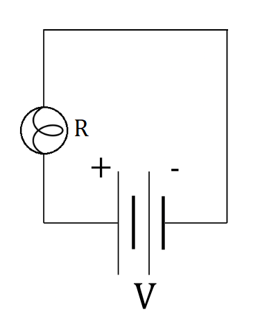
where $I$ is rated current for the lightbulb when it’s connected to the household socket and $R$ is resistance of the filament in the lightbulb. If we want to make sure that the lightbulb will light, we need to make sure that the current $I$ flowing through the lightbulb is high enough, which is easily possible if we don’t use any other resistors other than resistance of the filament. This means that the circuit diagram we need is really simple – we just connect the lightbulb to the voltage source, as in the figure below:
$$I=frac{V}{R}$$
Now, since we are taking a closer look at the resistance, we can extract it to get a better look at the connection between voltage and resistance:
$$R=frac{V}{I}$$
This conclusion would be true if the assumption of **constanst current** was valid. However, in realistic scenario, the resistance would change slightly, and the **current would increase** so that the ratio of voltage and current, also expressed by resistance, remains almost **constant**.
$$
I = dfrac{V}{R}
$$
As said in the problem text, we can express resistance $R$ from Ohm’s law as:
$$
R = dfrac{V}{I}
$$
One could fall for a trap that increasing the voltage $V$ will also increase the resistance $R$, but that’s not the case. Resistance $R$ of a resistor depends on the material from which the resistor is made from, its cross sectional area $A$ and its length $L$ . This means that for a certain given resistor with resistance $R$, its resistance won’t change unless you cut the resistor and change its cross sectional area $A$ or length $L$ or if you chemically mix it up with some other material because different materials have different specific resistance $rho$
In other words, changing the voltage across resistor $R$ will only change the current flowing through this resistor, but its resistance $R$ will be unaffected by change of the voltage.
Ohm’s law states that current $I$ flowing through a resistor with resistance $R$ and voltage $V$ across it is given as:
$$
I = dfrac{V}{R}
$$
We can express resistance $R$ of the resistor from the general equation above as:
$$
R = dfrac{V}{I}
$$
From the equation above we see that we can measure the resistance $R$ of the wire by measuring the voltage $V_R$ across this long piece of wire and current $I$ flowing through it by applying the following equation:
$$
begin{align*}
R = dfrac{V_R}{I} tag{1}
end{align*}
$$
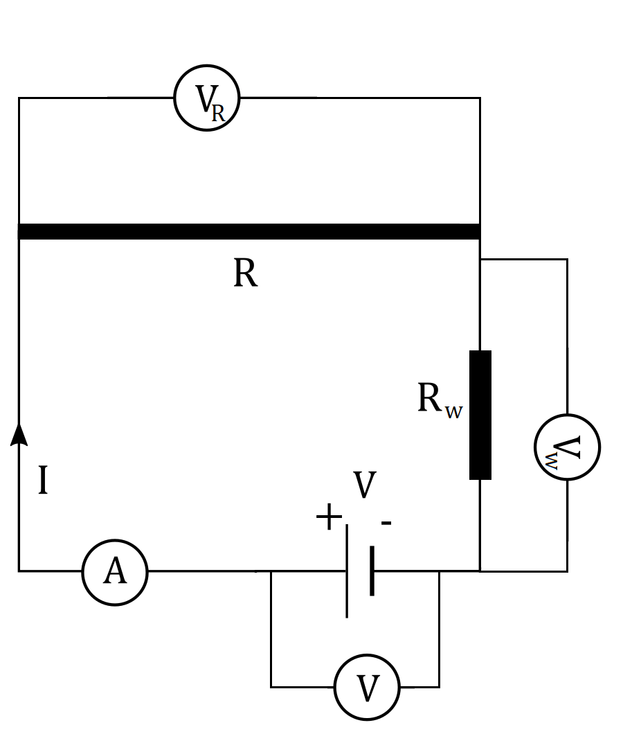
If we connect the ammeter in series with the long piece of wire and the battery, we can measure the current $I$ flowing through this piece of wire. To measure voltage $V_R$ across this long piece of wire could connect voltmeter in parallel with the long piece of wire, as shown in the figure below:
$$
V_V = V_R
$$
This means that we can truly measure voltage across the long piece of wire with resistance $R$ using the ammeter.
Consequence of idealizing the ammeter is that voltage drop $V_A$ across the ammeter is zero and that resistance of the ammeter won’t affect the total current supplied from the battery. This means that the same current $I$ supplied from the battery will flow from the ammeter and that we can use this ammeter to measure the current $I$ flowing through the long piece of wire with resistance $R$.
$$
R = rho dfrac{L}{A}
$$
where $rho$ is resistivity of the material, $L$ is length of the resistor and $A$ is cross-sectional area of the resistor. In our case, we’ll connect the ammeter with two ends of a long piece of wire with resistance $R$. This means that the wire we use to connect the ammeter must also be long and thus its length $L$ is not negligible. We can express the total resistance $R_w$ of the wire that we used to connect the ammeter as:
$$
begin{align*}
R_w = rho dfrac{L}{A} tag{2}
end{align*}
$$
If we know from which material this wire is made from, we know the resistivity $rho$ of this wire and by measuring the length $L$ and cross-sectional area $A$ of the wire used to connect the ammeter, we can find the total resistance of the wire $R_w$ used to connect the ammeter.
This whole wire can be represented with one single resistor $R_w$ shown in the figure above.
$$
I = dfrac{V}{R + R_w}
$$
We can multiply this equation by $(R + R_w)$ and have:
$$
IR + I R_w = V
$$
We can now express unknown resistance $R$ from the equation above:
$$
begin{align*}
IR &= V – I R_w \
tag{divide by $I$} \
R &= dfrac{V}{I} – dfrac{IR_w}{I} \
R &= dfrac{V}{I} – R_w tag{3}
end{align*}
$$
Resistance $R_w$ of the wire used to connect the ammeter can be expressed from equation $(2)$ as:
$$
R_w = rho dfrac{L}{A}
$$
We can now plug this into equation $(3)$ and have:
$$
begin{align*}
R &= dfrac{V}{I} – R_w \
R &= dfrac{V}{I} – rho dfrac{L}{A} tag{4} \
end{align*}
$$
At the beginning of this solution, we said that we’ll connect the voltmeter in parallel with the long piece of wire of unknown resistance $R$. If we connect it across the battery, we’ll measure voltage $V$ across the battery. Note that this won’t change the current $I$ flowing through the battery because voltmeter has infinite resistance.
Ammeter will measure current $I$ flowing through the battery. If we know the resistivity $rho$ of the wire we used to connect this circuit and connect the ammeter, measure its length $L$ and measure its cross-sectional area $A$, connect the circuit as shown in the figure above and measure voltage $V$ across the battery and current $I$ flowing in the circuit, we can measure resistance $R$ of this long piece of wire by using the following equation (equation $(4)$):
$$
boxed{ R = dfrac{V}{I} – rho dfrac{L}{A} }
$$
First we need to find an expression for power output in terms of known quantities – resistance and voltage.
Power output $P$ of an electric component connected to voltage $V$ with current $I$ flowing through it is calculated as:
$$
begin{align*}
P &= VI \
tag{plug in the current $I$ from Ohm’s law $I = dfrac{V}{R}$} \
P &= V dfrac{V}{R} \
P &= dfrac{V^2}{R} \
end{align*}
$$
For $P_i$ we find:
$$
begin{align*}
P_i &= dfrac{V^2}{R_i} \
tag{plug in the given values} \
P_i &= dfrac{( 12 ~mathrm{V})^2}{ 12 ~mathrm{Omega }} \
P_i &= dfrac{144 ~mathrm{V^2}}{12 ~mathrm{Omega}} \
P_i &= 12 ~mathrm{W}
end{align*}
$$
For $P_f$ we find:
$$
begin{align*}
P_f &= dfrac{V^2}{R_f} \
tag{plug in the given values} \
P_f &= dfrac{( 12 ~mathrm{V})^2}{ 12 ~mathrm{Omega }} \
P_f &= dfrac{144 ~mathrm{V^2}}{9 ~mathrm{Omega}} \
P_f&= 16 ~mathrm{W}
end{align*}
$$
Change in power $Delta P$ is calculated as:
$$
begin{align*}
Delta P &= P_f – P_i \
tag{plug in the calculated values} \
Delta P &= 16 ~mathrm{W} – 12 ~mathrm{W}
end{align*}
$$
$$
boxed{ Delta P = 4 ~mathrm{W}}
$$
Delta P = 4 ~mathrm{W}
$$
$$t_0=1cdot 60=60,,rm{s}$$
And $t$:
$$t=1cdot 60cdot 60=3600,,rm{s}$$
With that assumption made, we can write down an equation for nominal power that connects energy and time:
$$P_0=frac{E_0}{t_0}$$
Inserting values we get:
$$P_0=frac{2.2cdot 10^3}{3cdot 60}$$
$$P_0=12.22,,rm{W}$$
$$P_0=frac{E}{t}$$
From this we can extract $E$:
$$E=P_0t$$
Inserting values we get:
$$E=12.22cdot 1cdot 60cdot 60$$
Finally:
$$boxed{E=44,,rm{kJ}}$$
Energy $E$ delivered in time $t$ to the the circuit with power output $P$ can be found from the definition of power, which states that power $P$ is energy $E$ delivered in time interval $t$, stated as:
$$
begin{align*}
P &= dfrac{E_1}{t_1} \
tag{plug in the given values} \
P &= dfrac{2.2 cdot 10^3 ~mathrm{J}}{ 3 ~mathrm{min} } \
P &= dfrac{ 2.2 cdot 10^3 ~mathrm{J} }{ 3 cdot 60 ~mathrm{s} }
end{align*}
$$
$$
boxed{ P = 12.2222 ~mathrm{W} }
$$
Analogously, from the definition of power we have:
$$
begin{align*}
P &= dfrac{E_2}{t_2} \
tag{express $E_2$ from the equation above} \
E_2 &= P t_2 \
tag{plug in the calculated value of $P$ and given value of $t_2$} \
E_2 &= 12.2222 ~mathrm{W} cdot 1 ~mathrm{h} \
tag{$1~mathrm{h} = 3600 ~mathrm{s} $} \
E_2 &= 12.2222 ~mathrm{W} cdot 3600 ~mathrm{s}
end{align*}
$$
$$
boxed{E_2 = 44000 ~mathrm{J}}
$$
E_2 = 44000 ~mathrm{J}
$$
However, this is not necessarily bad. When current flows through a resistor on the electric stove, it heats up and we can use the stove to cook. Similar thing happens in the iron. When current flows through the resistor in a light bulb, it heats up to high temperatures and starts to glow.
