
All Solutions
Page 610: Assessment
Analogously, since the term on the bottom right is unit of measure for resistance, we conclude that solution for the field on the bottom right is resistance.
Since the terms on the bottom should all be units of measure, this means since the term on the field in the middle is power, solution for field in the bottom centre is unit of measure for power, which is watt.
$$
boxed{text{bottom left: current, ~~ bottom centre: watt, ~~ bottom right: resistance}}
$$
$$I=frac{q}{t}$$
$$boxed{[A]=frac{[C]}{[s]}}$$
$$
I = dfrac{q}{t}
$$
Unit of measure for electric current is Ampere $(mathrm{A})$, whereas unit for charge is Coulomb $(mathrm{C})$ and unit of measure for time is second $(mathrm{s})$. This means that 1 Ampere is defined in SI units as:
$$
1 ~mathrm{A} = dfrac{1 ~mathrm{C}}{1 ~mathrm{s}}
$$
$$
I = dfrac{q}{t}
$$

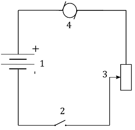

a) a device that converts electric energy to mechanical energy
b) a device that converts chemical energy to electric
c) a device that turns the circuit on and off
d) a device that provides a way to adjust speed
$$boxed{a) 4}$$
$$boxed{b) 1}$$
$$boxed{c) 2}$$
$$boxed{d) 3}$$
$$b) 1$$
$$c) 2$$
$$d) 3$$
$$
a. ~4
$$
$b)~~$ A battery uses electric energy and stores it as chemical energy. Battery in our circuit is labelled as $1$. We conclude that the final answer is
$$
b. ~1
$$
$c)~~$ A switch is used to turn the circuit on and off. Switch in this circuit is labelled as $2$. We conclude that the final answer is
$$
c. ~2
$$
$d)~~$ A variable resistor is used to adjust the resistance in the circuit which in turn adjusts the current in the circuit. We conclude that the final answer is
$$
d. ~ 3
$$
a. ~4
$$
$$
b. ~1
$$
$$
c. ~2
$$
$$
d. ~ 3
$$
incadesent lightbulb, a clothes dryer and a digital clock radio.
$b)~~$ Electric energy provided to the clothes dryer is partially used as heat (thermal energy) used to dry the clothes, while the rest of the energy is used as kinetic energy of the rotating bell and the kinetic energy of the warm air blown on the clothes.
$c)~~$ Electric energy provided to a digital clock radio is partially used as sound energy of the radio and partially used as light energy of the digital screen on the radio.
$$A=frac{d^2pi}{4}$$
From this equation we can see that the larger diameter means **larger cross-section area**.
$$R=frac{rho L}{A}$$
Where $rho$ is a specific conductivity and is a **property of the material**, meaning that for two wires of the same material it will remain **equal**.
Length $L$ is also not a factor since we are comparing two wires of the equal lengths.
And the **larger** the cross-section are, the **lower** the resistance.
$$
A = dfrac{d^2 pi }{4}
$$
Resistance $R$ of a wire with cross-sectional area $A$ and length $L$ is given as:
$$
R = dfrac{rho L}{A}
$$
where $rho$ is resistivity of the material from which the wire was made from.
From the equation above we see that resistance $R$ is inversely proportional to the cross-sectional area $A$, which means that the wire with greater cross-sectional area has lower resistance.
We can also understand a solution to this question physically, given that the current $I$ is defined as charge $q$ flowing through a cross-sectional area $A$ of a conductor in time $t$, which means that the greater the cross-sectional area, the more charges can flow through it in the same time interval.
text{ A wire with greater cross-sectional area has lower resistance }
$$
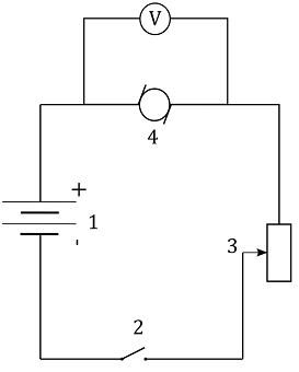
$a)~~$ Draw the circuit diagram
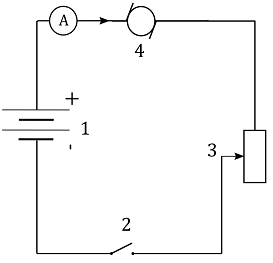
$b)~~$ Connect the ammeter so that it measures the current $I$ flowing in the circuit
$c)~~$ Connect the voltmeter so that it reads the voltage $V$ across the resistor.
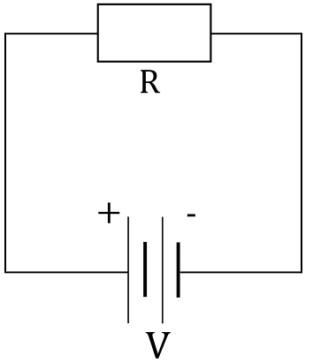

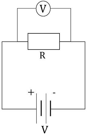
Since voltmeter is used to measure voltage across a certain device, if we connect it in parallel to the resistor $R$, voltage across this resistor will be the same as voltage across the voltmeter and reading on the voltmeter will show us the voltage across the resistor.
The end result is shown in the figure below, with voltmeter connected in parallel to the resistor:
begin{align*}
& a)~~ text{Connect the battery and the resistor in series by using the wires.} \
& b)~~ text{Connect the ammeter in series to the battery.} \
& c)~~ text{Connect the voltmeter in parallel to the resistor.} \
end{align*}
$$
While the light bulb is operating, filament in the light bulb already expanded and since it didn’t break during the sudden expanding when we turned it on, there’s no reason for it to break, other than short-circuit or other similar events that make any device burn out.
$$P=frac{V^2}{R}$$
where $V$ is voltage difference on the wire and $R$ is resitance. Copper wire has **low resistance** which then means that the amount of **current** flowing through it will be extremely **high**.
$$P=RI^2$$
Where the power is proportional to the square of electric current.
This power needs to leave the wire somehow, and it is done through the heat exchange. The sole mechanism of heat transfer can be explained by a high velocity of high number of **electrons** flowing through the wire, which due to **collisions** between them, increase the temperatuer of the wire.
$$
P = dfrac{V^2}{R}
$$
where $V$ is voltage across that component and $R$ is its resistance. Copper wire on its own has low electric resistance and voltage across the wire is equal to voltage across the battery. Dividing a square of square of the voltage across the battery with low electrical resistance of the copper wire gives us high power output on the copper wire. Note that all of the energy $E$ supplied by the battery, proportional to this high power output $P$ is transformed to heat in the copper wire. In other words, rate at which electric power is turned to heat in copper wire is high enough for an easily measurable change in the temperature of the copper wire.
Of course, copper wire will heat up from any current flowing through it, but most of the times you want to reduce the loss of electric energy to heat.
Power lost to heat, when there’s current $I$ flowing through the copper wire can also be expressed as
$$
P = I^2 R
$$
In short circuit, however, this isn’t possible because current is very high, which makes the friction between the electrons in the wire very high and greatly increases the loss of electric energy to heat.
$$
P = I^2 R
$$
where $R$ is resistance of the wire. Of course, to transfer the electric energy over long distances but keep the losses to heat minimal, power expressed in the equation above should be minimal, which means that current $I$ through the wire and its resistance $R$ should be kept small.
text{Current through the wire and its resistance}
$$
$$
P = dfrac{E}{t }
$$
If we take a look at the units of the physical quantities in the equation above, we have:
$$
begin{align*}
mathrm{ W = dfrac{J}{s} } tag{1}
end{align*}
$$
Energy $E$ needed to move an object by a distance $d$ with force $F$ acting on it in the direction of the displacement $d$ is equal to:
$$
E = F d
$$
If we take a look at the units of the physical quantities in the equation above, we have:
$$
mathrm{ J= dfrac{N}{m} }
$$
We can plug in the expression for Joule from the expression above into equation $(1)$ and have:
$$
begin{align*}
mathrm{ W = dfrac{N m }{s} } tag{2}
end{align*}
$$
$$
begin{align*}
F = dfrac{Delta p}{Delta t} tag{3}
end{align*}
$$
whereas momentum is defined as a product of mass $m$ and velocity $upsilon$ of an object, stated as:
$$
p = m upsilon
$$
which means that unit of measurement of momentum is
$$
p ~ [=] ~mathrm{kg ~dfrac{m}{s}}
$$
If we take a look at the units of physical quantities of the units in equation $(3)$ we have:
$$
mathrm{ N = dfrac{dfrac{kg m }{s} }{s} = dfrac{kg m}{s^2 } }
$$
We can plug in the expression for Newtons from the equation above into equation $(2)$ and find that one Watt is equal to:
$$
begin{align*}
mathrm{W} &= mathrm{ dfrac{N m }{s} } \
tag{plug in $ mathrm{ N = dfrac{kg m}{s^2 } } $} \
mathrm{W} &= dfrac{mathrm{ dfrac{kg m }{s^2 } cdot m}}{mathrm{s}}
end{align*}
$$
$$
boxed{ mathrm{W} = mathrm{dfrac{kg m^2}{s^3 } } }
$$
mathrm{W} = mathrm{dfrac{kg m^2}{s^3 } }
$$
$$
W = q Delta V
$$
This means that if there is potential difference, work will be done and charges will be moved. If we connect a battery to a complete circuit, this means that charges can flow from one terminal of the battery to the other and since there is potential difference $Delta V$ between the terminals of the battery, this means that charges will start to move and they’ll move through the electric current flowing through this circuit.
Whole wire is more or less on the same voltage. Voltage drops across great lengths and due to impurities in the wire. Keeping it in mind that birds claws are not far apart, when bird lands on the high-voltage wire, its claws will be on approximately the same electric potential, which makes the potential difference between its claws almost zero. This means that since electric potential difference (Voltage) across its claws is almost zero, there will be no current flowing through the bird. Let’s also add to this conclusion a fact that bird’s claws are made from a highly insulating material which further decreases the possibility of electric shock when bird lands on the wires.
$$I=frac{V}{R}$$
From this equation we can clearly see correlation between electrical current, voltage and resistance.
$$
I = dfrac{V}{R}
$$
As we can see, current $I$ is proportional to the potential difference $V$ across the terminals of the resistor $R$
$$
I propto V
$$
which means that if we increase the voltage used in the circuit, current will also increase and vice versa.
We can also see that current $I$ is inversely proportional to the resistance $R$ of the resistor
$$
I propto dfrac{1}{R}
$$
which means that if we decrease the resistance $R$ of the resistor, current $I$ through the resistor will increase.
$$P=frac{V^2}{R}$$
From this equation we can calculate the resistance as:
$$R=frac{V^2}{P}$$
This finally means that the **higher power rating** means **lower resistance**.
This finally means that the bulb with power rating of $P_1=50,,rm{W}$ has higher electric resistance.
$$
P = dfrac{V^2}{R}
$$
where $V$ is voltage across that component and $R$ is its resistance.
We can express resistance $R$ of the light bulb from the equation above as:
$$
R = dfrac{V^2}{P}
$$
As we can see, resistance $R$ is inversely proportional to the power rating $P$
$$
R propto dfrac{1}{P}
$$
which means that the higher the power rating the lower the electric resistance of the component and vice versa. Given that power rating $P_1 = 50 ~mathrm{W}$ is lower than power rating $P_2 = 100 ~mathrm{W}$ and both light bulbs operate on the same voltage $V ) 120 ~mathrm{V}$, we conclude that the light bulb with lower rating (the one with $50 ~mathrm{W}$) has higher electric resistance.
$$I=frac{V}{R}$$
Where $I$ is the current, $V$ is the voltage and $R$ is resitance.
$$I propto frac{1}{R}$$
Which means that the **increase** in resistance $R$ causes **decrease** in current $I$.
$$
I = dfrac{V}{R}
$$
We can see that current $I$ is inversely proportional to the resistance $R$ of the resistor
$$
I propto dfrac{1}{R}
$$
which means that if we decrease the resistance $R$ of the resistor, current $I$ through the resistor will increase and vice versa.
Since current $I$ is inversely proportional to the resistance $R$, this means that if we double the resistance $R$, current $I$ will drop to half of its original value.
$$I=frac{V}{R}$$
which gives relation between current, voltage and resistance of the circuit.
$$I_1=frac{V_1}{R_1}$$
And for the current in the second scenario:
$$I_2=frac{V_2}{R_2}$$
$$I_1=frac{V_1}{R_1}$$
And:
$$I_2=frac{2V_1}{2R_1}$$
$$boxed{I_2=I_1}$$
Which finally means that the current remains constant
$$
I = dfrac{V}{R}
$$
As we can see, current $I$ is proportional to the potential difference $V$ across the terminals of the resistor $R$
$$
I propto V
$$
which means that if we double the voltage used in the circuit, current will also double.
We can also see that current $I$ is inversely proportional to the resistance $R$ of the resistor
$$
I propto dfrac{1}{R}
$$
which means that if we double the resistance $R$ of the resistor, current $I$ through the resistor will decrease to half of its original value.
Current before doubling the voltage and resistance $I$ is equal to:
$$
I = dfrac{V}{R}
$$
If we both double the voltage across $V_2 = 2 V$ the resistor and double the resistance of the resistor $R_2 = 2 R$, we find that the current $I_2$ in this case is equal to:
$$
begin{align*}
I_2 &= dfrac{V_2}{R_2} \
tag{plug in $V_2 = 2 V$ and $R_2 = R$} \
I_2 &= dfrac{2 V}{ 2 R} \
tag{cancel out $2$} \
I_2 &= dfrac{V}{R} \
tag{notice that $I = dfrac{V}{R}$}
end{align*}
$$
$$
boxed{I_2 = I}
$$
As expected, doubling both the voltage across the resistor and resistance of the resistor will keep the same value of current.
$$I=frac{V}{R}$$
$$R=frac{V}{I}$$
$$R_1=frac{V_1}{I_1}$$
$$R_2=frac{V_2}{R_2}$$
$$R_1=frac{1.5}{45cdot 10^{-6}}$$
$$R_2=frac{3}{25cdot 10^{-3}}$$
Finally:
$$R_1=33.3,,rm{kOmega }$$
And
$$R_2=0.12,,rm{kOmega }$$
Which means that device **does not follow Ohm’s Law** because
$$boxed{R_1 neq R_2}$$
current $I$ flowing through a resistor with resistance $R$ and potential difference $V$ across the terminals of the resistor is equal to:
$$
I = dfrac{V}{R}
$$
We can express resistance $R$ from the equation above as:
$$
R = dfrac{V}{I}
$$
If this device is truly a resistor, its resistance $R$ will be the same in both of the cases and the equation above will hold for any combination of voltage $V$ and the corresponding measured current $I$ flowing through it.
In first case, voltage $V_1 = 1.5 ~mathrm{V}$ was applied to the device and current
$I_1 = 45 cdot 10^{-6} ~mathrm{A}$ was measured. Judging by the two quantities in this measurement, resistance $R_1$ measured in these conditions is:
$$
begin{align*}
R_1 &= dfrac{V_1}{I_1} \
tag{plug in the measured values} \
R_1 &= dfrac{1.5 ~mathrm{V} }{ 45 cdot 10^{-6} ~mathrm{A} } \
R_1 &= 0.033333 cdot 10^{6} ~mathrm{Omega } \
R_1 &= 33.333 cdot 10^{3} ~mathrm{Omega }
end{align*}
$$
$$
boxed{R_1 = 33.333 ~mathrm{k Omega}}
$$
In second case, voltage $V_2 = 3 ~mathrm{V}$ was applied to the device and current
$I_2 = 25 cdot 10^{-3} ~mathrm{A}$ was measured. Judging by the two quantities in this measurement, resistance $R_2$ measured in these conditions is:
$$
begin{align*}
R_2 &= dfrac{V_2}{I_2} \
tag{plug in the measured values} \
R_2 &= dfrac{3 ~mathrm{V} }{ 25 cdot 10^{-3} ~mathrm{A} } \
R_2 &= 0.12 cdot 10^{3} ~mathrm{Omega }
end{align*}
$$
$$
boxed{R_2 = 0.12 ~mathrm{k Omega}}
$$
everywhere in this circuit, our answer is yes.
textit{color{#c34632}$See$ $Explanation$}
$$
$$I=frac{V}{R}$$
$$P=IV$$
$$P=frac{V^2}{R}$$
From this we can see that with constant voltage, the higher the resistance the lower the power.
This means that the **higher rate of thermal energy production** will be with a wire with **lower resistance**.
$$
P = dfrac{V^2}{R}
$$
where $V$ is voltage across that component and $R$ is its resistance.
Notice that this power output is actually a rate at which thermal energy is produced in the resistor.
Note that the same voltage of $V = 6~mathrm{V}$ will be applied to both of the cases, one in which we use a high resistance wire and the other case where we use the low resistance wire. As we can see from the equation above, power output is inversely proportional to the resistance $R$ of that component, which means that the lower the resistance $R$, the higher the power output $P$.
We conclude that the wire with lower electric resistance will produce thermal energy at a faster rate.
text{Wire with lower electric resistance will produce thermal energy at a faster rate}
$$
Power output $P$ of an electric component connected to voltage $V$ with current $I$ flowing through it is calculated as:
$$
begin{align*}
P &= VI \
tag{plug in the given values} \
P &= 12 ~mathrm{V} cdot 1.50 ~mathrm{A}
end{align*}
$$
$$
boxed{ P = 18 ~mathrm{W} }
$$
$$
begin{align*}
P &= dfrac{E}{t} \
tag{express $E$ from the equation above} \
E &= P t \
tag{plug in the given values} \
E &= 18 ~mathrm{W} cdot 15 ~mathrm {min} \
tag{$mathrm{1 min = 60 ~mathrm{s }}$} \
E &= 18 ~mathrm{W} cdot 15 cdot 60 ~mathrm {s}
end{align*}
$$
$$
boxed{ E = 16200 ~mathrm{J} }
$$
a)~~ P = 18 ~mathrm{W}
$$
$$
b)~~ E = 16200 ~mathrm{J}
$$
From Ohm’s law we know that the current $I$ flowing through an electric component with resistance $R$ with voltage $V$ across the component is calculated as:
$$
I = dfrac{V}{R}
$$
Keep in mind that voltage across the $R= 18 ~mathrm{Omega}$ resistor is $V = 27 ~mathrm{V}$. Current $I$ through the resistor $R$ is calculated as:
$$
begin{align*}
I &= dfrac{V}{R} \
tag{plug in the given values} \
I &= dfrac{ 27 ~mathrm{V} }{ 18 ~mathrm{Omega}}
end{align*}
$$
$$
boxed{ I = 1.5 ~mathrm{A} }
$$
$$
boxed{ V_{voltmeter} = V = 27 ~mathrm{V} }
$$
Power output $P$ of an electric component connected to voltage $V$ with current $I$ flowing through it is calculated as:
$$
begin{align*}
P &= VI \
tag{plug in the given values} \
P &= 27 ~mathrm{V} cdot 1.5 ~mathrm{A}
end{align*}
$$
$$
boxed{ P = 40.5 ~mathrm{W} }
$$
$$
begin{align*}
P &= dfrac{E}{t} \
tag{express $E$ from the equation above} \
E &= P t \
tag{we’re interested in energy $E$ delivered in $t = 1 ~mathrm{h}$} \
tag{plug in the given values} \
E &= 40.5 ~mathrm{W} cdot 1 ~mathrm {h} \
tag{$mathrm{1 h = 3600 ~mathrm{s } }$} \
E &= 40.5 ~mathrm{W} cdot 3600 ~mathrm{s }
end{align*}
$$
$$
boxed{ E = 145800 ~mathrm{J} }
$$
a)~~ I = 1.5 ~mathrm{A}
$$
$$
b)~~ V_{voltmeter} = 27 ~mathrm{V}
$$
$$
c)~~ P = 40.5 ~mathrm{W}
$$
$$
d)~~ E = 145800 ~mathrm{J}
$$
From Ohm’s law we know that the current $I$ flowing through an electric component with resistance $R$ with voltage $V$ across the component is calculated as:
$$
I = dfrac{V}{R}
$$
Keep in mind that voltage across the $9 ~mathrm{Omega}$ resistor $R$ is $V = 27 ~mathrm{V}$. Current $I$ through the resistor $R$ is calculated as:
$$
begin{align*}
I &= dfrac{V}{R} \
tag{plug in the given values} \
I &= dfrac{ 27 ~mathrm{V} }{ 9 ~mathrm{Omega}}
end{align*}
$$
$$
boxed{ I = 3 ~mathrm{A} }
$$
$$
boxed{ V_{voltmeter} = V = 27 ~mathrm{V} }
$$
Power output $P$ of an electric component connected to voltage $V$ with current $I$ flowing through it is calculated as:
$$
begin{align*}
P &= VI \
tag{plug in the given values} \
P &= 27 ~mathrm{V} cdot 3 ~mathrm{A}
end{align*}
$$
$$
boxed{ P = 81 ~mathrm{W} }
$$
$$
begin{align*}
P &= dfrac{E}{t} \
tag{express $E$ from the equation above} \
E &= P t \
tag{we’re interested in energy $E$ delivered in $t = 1 ~mathrm{h}$} \
tag{plug in the given values} \
E &= 81 ~mathrm{W} cdot 1 ~mathrm {h} \
tag{$mathrm{1 h = 3600 ~mathrm{s } }$} \
E &= 81 ~mathrm{W} cdot 3600 ~mathrm{s }
end{align*}
$$
$$
boxed{ E = 291600 ~mathrm{J} }
$$
a)~~ I = 3 ~mathrm{A}
$$
$$
b)~~ V_{voltmeter} = 27 ~mathrm{V}
$$
$$
c)~~ P = 81 ~mathrm{W}
$$
$$
d)~~ E = 291600 ~mathrm{J}
$$
From Ohm’s law we know that the current $I$ flowing through an electric component with resistance $R$ with voltage $V$ across the component is calculated as:
$$
I = dfrac{V}{R}
$$
Keep in mind that voltage across the $18 ~mathrm{Omega}$ resistor $R$ is $V = 9 ~mathrm{V}$. Current $I$ through the resistor $R$ is calculated as:
$$
begin{align*}
I &= dfrac{V}{R} \
tag{plug in the given values} \
I &= dfrac{ 9 ~mathrm{V} }{ 18 ~mathrm{Omega}}
end{align*}
$$
$$
boxed{ I = 0.5 ~mathrm{A} }
$$
$$
boxed{ V_{voltmeter} = V = 9 ~mathrm{V} }
$$
Power output $P$ of an electric component connected to voltage $V$ with current $I$ flowing through it is calculated as:
$$
begin{align*}
P &= VI \
tag{plug in the given values} \
P &= 9 ~mathrm{V} cdot 0.5 ~mathrm{A}
end{align*}
$$
$$
boxed{ P = 4.5 ~mathrm{W} }
$$
$$
begin{align*}
P &= dfrac{E}{t} \
tag{express $E$ from the equation above} \
E &= P t \
tag{we’re interested in energy $E$ delivered in $t = 1 ~mathrm{h}$} \
tag{plug in the given values} \
E &= 4.5 ~mathrm{W} cdot 1 ~mathrm {h} \
tag{$mathrm{1 h = 3600 ~mathrm{s } }$} \
E &= 4.5 ~mathrm{W} cdot 3600 ~mathrm{s }
end{align*}
$$
$$
boxed{ E = 16200 ~mathrm{J} }
$$
a)~~ I = 0.5 ~mathrm{A}
$$
$$
b)~~ V_{voltmeter} = V = 9 ~mathrm{V}
$$
$$
c)~~ P = 4.5 ~mathrm{W}
$$
$$
d)~~ E =16200 ~mathrm{J}
$$
$$P=VI$$
Where it states that the power is equal to the voltage times current.
$$P=120cdot 8$$
Finally:
$$boxed{P=960,,rm{W}}$$
Power $P$ dissipated on an electric component connected to voltage $V$ with current $I$ flowing through it is calculated as:
$$
begin{align*}
P &= VI \
tag{plug in the given values} \
P &= 120 ~mathrm{V} cdot 8 ~mathrm{A}
end{align*}
$$
$$
boxed{ P = 960 ~mathrm{W} }
$$
P = 960 ~mathrm{W}
$$
$$P=VI$$
Where $P$ is power, $I$ is current in the bulb and $V$ is the voltage.
$$P=120cdot 1.2$$
Finally:
$$boxed{P=144,,rm{W}}$$
Power $P$ dissipated on an electric component connected to voltage $V$ with current $I$ flowing through it is calculated as:
$$
begin{align*}
P &= VI \
tag{plug in the given values} \
P &= 120 ~mathrm{V} cdot 1.2 ~mathrm{A}
end{align*}
$$
$$
boxed{ P = 144 ~mathrm{W} }
$$
P = 144 ~mathrm{W}
$$
$$P=VI$$
Where $P$ is power, $I$ is current and $V$ is voltage.
We can use this equation because in this case **the power delivered is equal to the power output** of the device.
$$P=120cdot 0.5$$
Finally, the power delivered is
$$boxed{P=60,,rm{W}}$$
$$P=frac{E}{t}$$
We can easily extract $E$:
$$E=Pt$$
$$E=60cdot 5cdot 60$$
Where $t$ is expressed in SI units, seconds.
Finally we get:
$$boxed{E=18,,rm{kJ}}$$
$$E=18,,rm{kJ}$$
We need to find the electric energy $E$ delivered to the lamp in
time interval $t = 5 ~mathrm{min}$.
Power output $P$ of an electric component connected to voltage $V$ with current $I$ flowing through it is calculated as:
$$
begin{align*}
P &= VI \
tag{plug in the given values} \
P &= 120 ~mathrm{V} cdot 0.5 ~mathrm{A} \
P &= 60 ~mathrm{W}
end{align*}
$$
Energy $E$ delivered in time $t$ to the component in the circuit with power output $P$ can be found from the definition of power, which states that power $P$ is energy $E$ delivered in time interval $t$, stated as:
$$
begin{align*}
P &= dfrac{E}{t} \
tag{express $E$ from the equation above} \
E &= P t \
tag{plug in the given values} \
E &= 60 ~mathrm{W} cdot 5 ~mathrm{min} \
tag{$mathrm{1 min = 60 ~mathrm{s}}$} \
E &= 60 ~mathrm{W} cdot 5cdot 60 ~mathrm{s} \
E &= 18000 ~mathrm{J}
end{align*}
$$
$$
boxed{ E = 18 ~mathrm{kJ} }
$$
E = 18 ~mathrm{kJ}
$$
Energy delivered in a period of time can be calculated as:
$$E=Pt$$
Where, in our case, $t=1,,rm{s}$.
And power can be calculated as:
$$P=VI$$
$$E=VIt$$
$$E=12cdot 210cdot 1$$
Finally:
$$boxed{E=2520,,rm{J}}$$
$$P=VI$$
$$P=12cdot 210$$
Finally the power output is:
$$boxed{P=2520,,rm{W}}$$
$$P=2520,,rm{W}$$
is $V = 12 ~mathrm{V}$ and that current $I$ flowing through the motor is $I = 210 ~mathrm{A}$. Keep in mind that this voltage $V$ is also voltage across the starter motor.
We need to find the electric energy $E$ delivered to the starter motor in
time $t = 1 ~mathrm{s}$.
$a)~~$ Energy $E$ delivered in time $t$ to the component in the circuit with current $I$ flowing through it and voltage $V$ across it is given as:
$$
begin{align*}
E &= P t \
tag{plug in the given values} \
E &= 12 ~mathrm{V} cdot 210 ~mathrm{A} cdot 1 ~mathrm{s}
end{align*}
$$
$$
boxed{ E = 2520 ~mathrm{J} }
$$
$b)~~$ Power $P$ supplied to an electric component connected to voltage $V$ with current $I$ flowing through it is calculated as:
$$
begin{align*}
P &= VI \
tag{plug in the given values} \
P &= 12 ~mathrm{V} cdot 210 ~mathrm{A}
end{align*}
$$
$$
boxed{ P = 2520 ~mathrm{W} }
$$
a)~~ E = 2520 ~mathrm{J}
$$
$$
b)~~ P = 2520 ~mathrm{W}
$$
$$P=VI$$
From this equation we can extract current $I$:
$$I=frac{P}{V}$$
$$I=frac{4200}{220}$$
Finally, the current on the device is:
$$boxed{I=19.1,,rm{A}}$$
Power output $P$ of an electric device connected to voltage $V$ with current $I$ flowing through it is calculated as:
$$
begin{align*}
P &= VI \
tag{express $I$ from the equation above} \
I &= dfrac{P}{V} \
tag{plug in the given values} \
I &= dfrac{4200 ~mathrm{W}}{220 ~mathrm{V}}
end{align*}
$$
$$
boxed{ I = 19.09 ~mathrm{A} }
$$
I = 19.09 ~mathrm{A}
$$
We need to find the power rating $P$ of the bulb and electric energy $E$ delivered to the flashlight bulb in time interval $t = 11 ~mathrm{min}$.
Power output $P$ of an electric component connected to voltage $V$ with current $I$ flowing through it is calculated as:
$$
begin{align*}
P &= VI \
tag{plug in the given values} \
P &= 3 ~mathrm{V} cdot 1.5 ~mathrm{A}
end{align*}
$$
$$
boxed{ P = 4.5 ~mathrm{W} }
$$
$$
begin{align*}
P &= dfrac{E}{t} \
tag{express $E$ from the equation above} \
E &= P t \
tag{plug in the given values} \
E &= 4.5 ~mathrm{W} cdot 11 ~mathrm{min} \
tag{$mathrm{1 min = 60 ~mathrm{s}}$} \
E &= 4.5 ~mathrm{W} cdot 11 cdot 60 ~mathrm{s}
end{align*}
$$
$$
boxed{ E = 2970 ~mathrm{J} }
$$
a)~~ P = 4.5 ~mathrm{W}
$$
$$
b)~~ E = 2970 ~mathrm{J}
$$
$$I=frac{V}{R}$$
$$V=IR$$
$$V=0.4cdot 60$$
Finally the voltage on the battery is:
$$boxed{V=24,,rm{V}}$$
$$
I = dfrac{V}{R}
$$
In this problem we have a current $I = 0.4 ~mathrm{A}$ flowing through a resistor with resistance of $R = 60 ~mathrm{Omega}$ connected across the unknown voltage $V$.
Current $I$ through the resistor is calculated as:
$$
begin{align*}
I &= dfrac{V}{R} \
tag{express $V$ from the equation above} \
V &= I R \
tag{plug in the given values} \
V &= 0.4 ~mathrm{A} cdot 60 ~mathrm{Omega}
end{align*}
$$
$$
boxed{ V = 24 ~mathrm{V} }
$$
V = 24 ~mathrm{V}
$$
$$I=frac{V}{R}$$
$$V=IR$$
$$V=1.5cdot 4$$
Finally, the voltage applied to the device is:
$$boxed{V=6,,rm{V}}$$
$$
I = dfrac{V}{R}
$$
In this problem we have a current $I = 1.5 ~mathrm{A}$ flowing through a resistor with resistance of $R = 4 ~mathrm{Omega}$ connected across the unknown voltage $V$.
Current $I$ through the resistor is calculated as:
$$
begin{align*}
I &= dfrac{V}{R} \
tag{express $V$ from the equation above} \
V &= I R \
tag{plug in the given values} \
V &= 1.5 ~mathrm{A} cdot 4 ~mathrm{Omega}
end{align*}
$$
$$
boxed{ V = 6 ~mathrm{V} }
$$
V = 6 ~mathrm{V}
$$
$$I=frac{V}{R}$$
$$V=IR$$
$$V=8cdot 15$$
Finally, the voltage on the device is:
$$boxed{V=120,,rm{V}}$$
$$
I = dfrac{V}{R}
$$
In this problem we have a current $I = 8 ~mathrm{A}$ flowing through a motor with resistance of $R = 15 ~mathrm{Omega}$ connected across the unknown voltage $V$.
Current $I$ through the motor is calculated as:
$$
begin{align*}
I &= dfrac{V}{R} \
tag{express $V$ from the equation above} \
V &= I R \
tag{plug in the given values} \
V &= 8 ~mathrm{A} cdot 15 ~mathrm{Omega}
end{align*}
$$
$$
boxed{ V = 120 ~mathrm{V} }
$$
V = 120 ~mathrm{V}
$$
$$I=frac{V}{R}$$
$$I=frac{75}{15}$$
Finally, the current in the resistor is:
$$boxed{I=5,,rm{A}}$$
$$
I = dfrac{V}{R}
$$
In this problem we have a resistor with resistance of $R = 15 ~mathrm{Omega}$ with voltage $V = 75 ~mathrm{V}$ across it. Current $I$ through the resistor is calculated as:
$$
begin{align*}
I &= dfrac{V}{R} \
tag{plug in the given values} \
I &= dfrac{ 75 ~mathrm{V} }{ 15 ~mathrm{Omega}}
end{align*}
$$
$$
boxed{ I = 5 ~mathrm{A} }
$$
I = 5 ~mathrm{A}
$$
Students then measured the current $I$ flowing through the nichrome wire for each chosen value of voltage $V$ across the wire. Notice that since wire is the only resistors in the circuit, voltage across the wire is equal to voltage $V$ across the supply. We must:
$a)~~$ Find resistance $R$ of the wire for each measurement
$b)~~$ Graph current $I$ versus voltage $V$
$c)~~$ Determine if the nichrome wire obeys the Ohm’s law.
Ohm’s law states that the current $I$ flowing through a resistor with resistance $R$ can be calculated as:
$$
I = dfrac{V}{R}
$$
where $V$ is voltage across the resistor. In this case, resistor in question is the mentioned nichrome wire.
We can express resistance $R$ of the nichrome wire from the equation above as:
$$ R = dfrac{V}{I} $$
In this problem, we’ll change the voltage $V$ across the wire, measure the current $I$ flowing through it and determine the resistance $R$ for each of the measurements by plugging in the measured values of voltage $V$ and current $I$. For example, for the first measurement we have:
$$ R_1 = dfrac{V_1}{I_1} $$
where $V_1$ is voltage we’ve applied across the wire in the first measurement, $I_1$ is current measured in the first measurement and $R_1$ is resistance of the nichrome wire in the first scenario, when voltage $V_1$ is applied and current $I_1$ is measured. We find that resistance $R_1$ is equal to:
begin{align*}
R_1 &= dfrac{V_1}{I_1} \
tag{plug in the values} \
R_1 &= dfrac{ 2 ~mathrm{V} }{ 0.014 ~mathrm{A} }
end{align*}
All other values of the resistance for each of the measurements are calculated analogously to the example above.
begin{table}[htb]
begin{tabular}{|l|l|l|ll}
cline{1-3}
Voltage, V (volts) & Current, I (amps) & Resistance, $ R= dfrac{V}{I} $ (ohms) & & \ cline{1-3}
2 & 0.014 & 142.857 & & \ cline{1-3}
4 & 0.027 & 148.148 & & \ cline{1-3}
6 & 0.04 & 150 & & \ cline{1-3}
8 & 0.052 & 153.846 & & \ cline{1-3}
10 & 0.063 & 158.73 & & \ cline{1-3}
-2 & -0.014 & 142.857 & & \ cline{1-3}
-4 & -0.028 & 142.857 & & \ cline{1-3}
-6 & -0.039 & 153.846 & & \ cline{1-3}
-8 & -0.051 & 156.862 & & \ cline{1-3}
-10 & -0.062 & 161.29 & & \ cline{1-3}
end{tabular}
end{table}
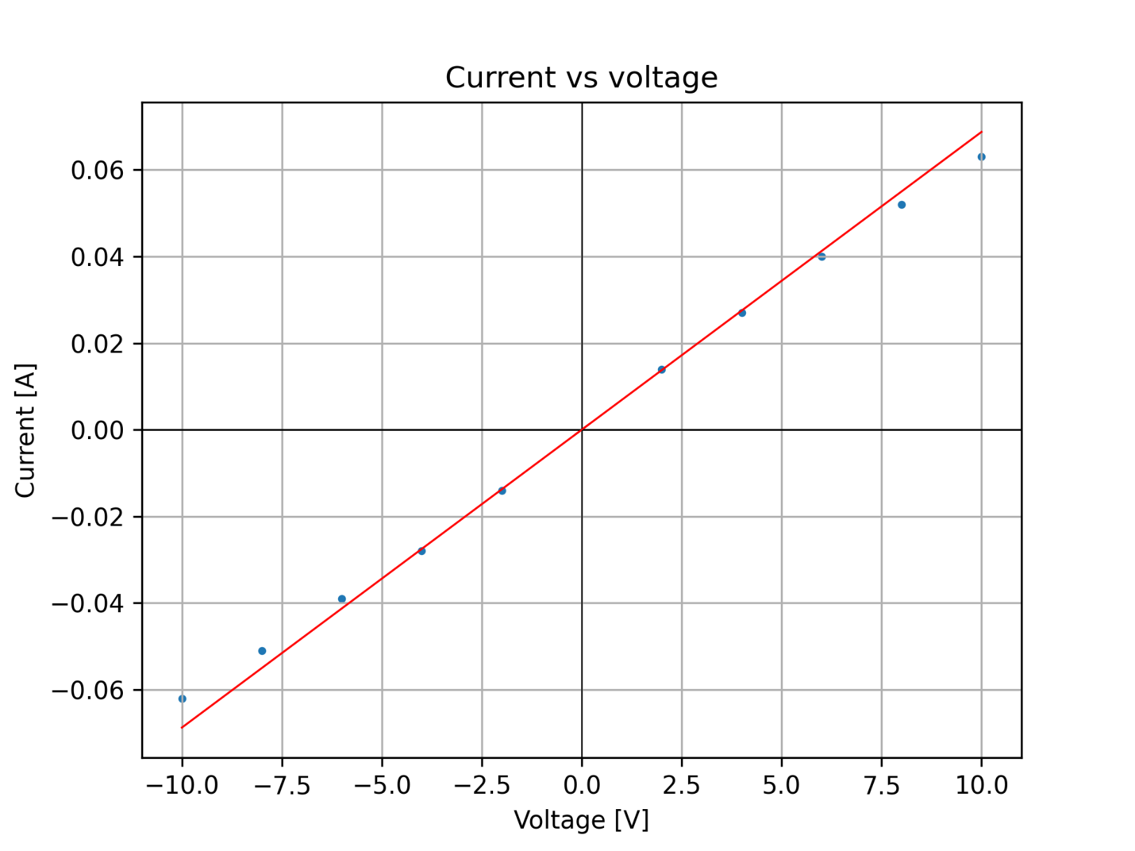
Blue dots represent measured values. We can see that for voltages below $V=-4 mathrm{~V}$ and above $V=4 mathrm{~V}$ measured values are much different than the values that we should have measured. In other words, blue dots are distant to the red line. This means that this wire obeys the Ohm’s law for voltage range between $V=-4 mathrm{~V}$ and $V=4 mathrm{~V}$.
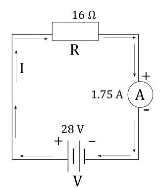
To draw a circuit diagram, we first conclude that this is a simple circuit, consisting only of a resistor $R$ and battery with voltage $V$ connected in series.
$$
I = dfrac{V}{R}
$$
We can express voltage $V$ across the battery from the equation above:
$$
begin{align*}
V &= I R \
tag{plug in the values } \
V &= 1.75 ~mathrm{A} cdot 16 ~mathrm{Omega}
end{align*}
$$
$$
boxed{V = 28 ~mathrm{V} }
$$
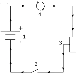
Now that we have voltage $V$ across the battery, we can draw a battery in the circuit and indicate positive and negative terminal of the battery and direction of the current $I$ accordingly. In other words, current must flow through a circuit from positive to a negative terminal of the battery, as shown in the figure below:
a)~~
$$
Ohm’s law states that
current $I$ flowing through a resistor with resistance $R$ and potential difference $V$ across the terminals of the resistor is equal to:
$$
I = dfrac{V}{R}
$$
We can express resistance $R$ from the equation above as:
$$
R = dfrac{V}{I}
$$
If this device obeys Ohm’s law, ratio of voltage applied in the first case and measured current when that voltage is applied will always be the same, because, as stated in the equation above, resistance is a constant.
In first case, voltage $V_1 = 6 ~mathrm{V}$ was applied to the device and current
$I_1 = 66 ~mathrm{mA}$ was measured. Judging by the two quantities in this measurement, resistance $R_1$ measured in these conditions is:
$$
begin{align*}
R_1 &= dfrac{V_1}{I_1} \
tag{plug in the measured values} \
R_1 &= dfrac{6 ~mathrm{V} }{ 66 ~mathrm{mA} } \
tag{$1~mathrm{mA} = 1 cdot 10^{-3} ~mathrm{A} $} \
R_1 &= dfrac{6 ~mathrm{V} }{ 66 cdot 10^{-3} ~mathrm{A} }
end{align*}
$$
$$
boxed{R_1 = 90.909 ~mathrm{Omega }}
$$
In second case, voltage $V_2 = 9 ~ mathrm{V}$ was applied to the device and current
$I_2 = 75 ~mathrm{mA}$ was measured. Judging by the two quantities in this measurement, resistance $R_2$ measured in these conditions is:
$$
begin{align*}
R_2 &= dfrac{V_2}{I_2} \
tag{plug in the measured values} \
R_2 &= dfrac{9 ~ mathrm{V} }{ 75 ~mathrm{mA} } \
tag{$1~mathrm{mA} = 1 cdot 10^{-3} ~mathrm{A} $} \
R_2 &= dfrac{9 ~ mathrm{V} }{ 75 cdot 10^{-3} ~mathrm{A} }
end{align*}
$$
$$
boxed{R_2 = 120 ~mathrm{ Omega} }
$$
Power output $P$ of an electric component connected to voltage $V$ with current $I$ flowing through it is calculated as:
$$
begin{align*}
P_1 &= V_1 I_1 \
tag{plug in the given values} \
P_1 &= 6 ~mathrm{V} cdot 66 ~mathrm{mA} \
tag{$1~mathrm{mA} = 1 cdot 10^{-3} ~mathrm{A} $} \
P_1 &= 6 ~mathrm{V} cdot 66 cdot 10^{-3} ~mathrm{A}
end{align*}
$$
$$
boxed{ P_1 = 0.396 ~mathrm{W} }
$$
Power output $P$ of an electric component connected to voltage $V$ with current $I$ flowing through it is calculated as:
$$
begin{align*}
P_2 &= V_2 I_2 \
tag{plug in the given values} \
P_2 &= 9 ~mathrm{V} cdot 75 ~mathrm{mA} \
tag{$1~mathrm{mA} = 1 cdot 10^{-3} ~mathrm{A} $} \
P_2 &= 9 ~mathrm{V} cdot 75 cdot 10^{-3} ~mathrm{A}
end{align*}
$$
$$
boxed{ P_2= 0.675 ~mathrm{W} }
$$
text{a)~~ Lamp doesn’t obey the Ohm’s law}
$$
$$
b)~~P_1 = 0.396 ~mathrm{W}
$$
$$
c)~~ P_2= 0.675 ~mathrm{W}
$$
$$P=frac{E}{t}$$
From this equation we can extract energy:
$$E=Pt$$
$$t=0.5,,rm{h}=0.5cdot 3600 ,,rm{s}$$
$$t=1800,,rm{s}$$
$$E=60cdot 1800$$
$$boxed{E=108,,rm{kJ}}$$
$$f_t=1-f=1-0.12=0.88$$
is converted into heat.
$$E_t=Ecdot f_t$$
Inserting values we get:
$$E_t=108cdot 0.88$$
$$boxed{E_t=95.04,,rm{kJ}}$$
$$E_t=95.04,,rm{kJ}$$
Total energy $E$ that the lightbulb uses in a given time interval of
$t = dfrac{1}{2} ~mathrm{h}$ is equal to a product of its total power rating and this time interval:
$$
begin{align*}
E &= P t \
E &= 60 ~mathrm{W} cdot dfrac{1}{2} ~mathrm{h} \
tag{$ mathrm{1 h = 3600 s} $} \
E &= 60 ~mathrm{W} cdot dfrac{1}{2} cdot 3600 mathrm{ s} \
E &= 108 000 ~mathrm{J}
end{align*}
$$
We find that the total energy used by this lightbulb in half an hour is equal to:
$$
boxed{ E = 108 ~mathrm{kJ} }
$$
To find the thermal energy $E_{thermal}$ that the lightbulb generates in half an hour, we’ll multiply its power of generating thermal energy $P_{thermal}$ with a given time interval $t = dfrac{1}{2} ~mathrm{h}$. Notice that the power of generating thermal energy $P_{thermal}$ is not given, but since we’re told that the lightbulb uses 12% of its electric energy to light, this means that the rest of the energy provided to the lightbulb is used as thermal energy, which is 88% of the total energy.
This means that in half an hour, 88% of the energy $E$ used by the lightbulb, calculated above, is used as thermal energy:
$$
begin{align*}
E_{thermal} &= 88% E \
E_{thermal} &= 0.88 E \
tag{plug in the given values} \
E_{thermal} &= 0.88 cdot 108 ~mathrm{kJ}
end{align*}
$$
$$
boxed{ E_{thermal} = 95.04 ~mathrm{kJ} }
$$
E = 108 ~mathrm{kJ}
$$
$$
E_{thermal} = 95.04 ~mathrm{kJ}
$$
$$
I = dfrac{V}{R}
$$
In this problem we have a current $I = 0.4 ~mathrm{A}$ flowing through a lamp with unknown resistance of $R$ with voltage $V = 120 ~mathrm{V}$ across it.
Current $I$ through the sensor circuit is calculated as:
$$
begin{align*}
I &= dfrac{V}{R} \
tag{express $R$ from the equation above} \
R &= dfrac{V}{I} \
tag{plug in the given values} \
R &= dfrac{120 ~mathrm{V} }{0.4 ~mathrm{A}}
end{align*}
$$
$$
boxed{ R = 300 ~mathrm{Omega} }
$$
$$
begin{align*}
R_{cold} &= dfrac{R}{5 } \
tag{plug in the given values}\
R_{cold} &= dfrac{300 ~mathrm{Omega }}{5}
end{align*}
$$
$$
boxed{ R_{cold} = 60 ~mathrm{Omega } }
$$
$$
begin{align*}
I_{cold} &= dfrac{V}{R_{cold}} \
tag{plug in the given values} \
I_{cold} &= dfrac{ 120 ~mathrm{V} }{60 ~mathrm{Omega } }
end{align*}
$$
$$
boxed{ I_{cold} = 2 ~mathrm{A } }
$$
begin{align*}
&a)~~ R = 300 ~mathrm{Omega} \
&b)~~ R_{cold} = 60 ~mathrm{Omega } \
&c)~~ I_{cold} = 2 ~mathrm{A }
end{align*}
$$
$a)~~$ If we apply a potential difference (Voltage) of $V_1 = 0.7 ~mathrm{V}$ across the diode, as we can see when we read the corresponding current from the graph, a current of $I_1 = 0.02 ~mathrm{A}$ flows through the diode. To find the resistance of the diode in this situation, we’ll apply the Ohm’s law which states that the current $I$ through an electric device with resistance $R$ connected to voltage $V$ is calculated as:
$$
begin{align*}
I &= dfrac{V }{R} \
tag{If we apply the Ohm’s law to this situation, we have:} \
I_1 &= dfrac{V_1}{R_1} \
tag{express $R_1$ from the equation above } \
R_1 &= dfrac{V_1}{I_1} \
tag{plug in the given values} \
R_1 &= dfrac{ 0.7 ~mathrm{V} }{0.02 ~mathrm{A} }
end{align*}
$$
$$
boxed{ R_1 = 35 ~mathrm{Omega } }
$$
$$
begin{align*}
I &= dfrac{V }{R} \
tag{If we apply the Ohm’s law to this situation, we have:} \
I_2 &= dfrac{V_2}{R_2} \
tag{express $R_2$ from the equation above } \
R_2 &= dfrac{V_2}{I_2} \
tag{plug in the given values} \
R_2 &= dfrac{ 0.6 ~mathrm{V} }{0.006 ~mathrm{A} }
end{align*}
$$
$$
boxed{ R_2 = 100 ~mathrm{Omega } }
$$
a)~~ R_1 = 35 ~mathrm{Omega }
$$
$$
b)~~ R_2 = 100 ~mathrm{Omega }
$$
$$
c)~~ text{ Hint: Current $I$ grows exponentially with voltage $V$ }
$$
$$
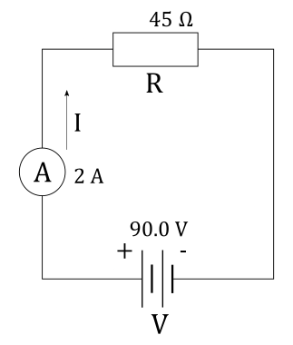
begin{align*}
I &= dfrac{V}{R} \
tag{plug in the values} \
I &= dfrac{90 ~mathrm{V}}{45 ~mathrm{Omega}} \
I &= 2 ~mathrm{A}
end{align*}
$$
Since this is a series circuit, this same current will flow through the whole circuit and reading on the ammeter will show this current. The end result of the circuit diagram is shown in the figure below, where current flows clockwise in order for it to flow from the positive terminal of the battery to negative terminal of the battery.
Total energy $E$ supplied from the battery is found as a product of voltage $V$ across its terminals, current $I$ supplied from it and time $t$ that it takes to “empty” the battery, stated as:
$$
begin{align*}
E &= I V t \
tag{plug in the given values} \
E &= 0.025 ~mathrm{A} cdot 9 ~mathrm{V} cdot 26 ~mathrm{h} \
E &= 5.85 ~mathrm{Wh} \
tag{ $ 1 ~mathrm{Wh = 10^{-3} ~mathrm{kWh}}$} \
E &= 5.85 cdot 10^{-3} ~mathrm{kWh}
end{align*}
$$
We found that the total energy stored in the battery, expressed in $~mathrm{kWh}$ is
$E = 5.85 cdot 10^{-3} ~mathrm{kWh}$
Now that we know how much energy is supplied from one battery, to find cost per kWh using the batteries, we’ll divide the cost of one battery with energy stored on it:
$$
begin{align*}
C_{per~kWh} &= dfrac{Cost}{E} \
tag{plug in the values} \
C_{per~kWh} &= dfrac{3 ~mathrm{$} }{5.85 cdot 10^{-3} ~mathrm{kWh}}
end{align*}
$$
$$
boxed{ C_{per~kWh} = 512.82 ~mathrm{dfrac{$}{kWh}} }
$$
C_{per~kWh} = 512.82 ~mathrm{dfrac{$}{kWh}}
$$
$$P=I^2R$$
$$I^2=frac{P}{R}$$
$$I=sqrt{frac{P}{R}}$$
$$I=sqrt{frac{5}{220}}$$
Finally:
$$boxed{I=0.151,,rm{A}}$$
$$
P = I^2 R
$$
where $P$ is its power rating, $R$ is its resistance and $I$ its current rating. We can express $I$ from the equation above as:
$$
begin{align*}
I^2 &= dfrac{P}{R} \
tag{find square root of the equation} \
I &= sqrt{dfrac{P}{R}} \
tag{plug in the given values} \
I &= sqrt{dfrac{ 5 ~mathrm{W} }{220 ~mathrm{ ~Omega }}} \
I &= sqrt{0.022727 ~mathrm{A^2}}
end{align*}
$$
$$
boxed{I = 0.15076 ~mathrm{A}}
$$
I = 0.15076 ~mathrm{A}
$$
$$P=VI$$
$$P=110cdot 3$$
$$P=330,,rm{W}$$
$$P=frac{E}{t}$$
$$E=Pt$$
$$t=1,,rm{h}=3600,,rm{s}$$
$$E=330cdot 3600$$
$$boxed{E=1.188,,rm{MJ}}$$
We need to find the thermal energy $E$ developed on the electric iron in
time $t = 1 ~mathrm{h}$. Keep in mind that the developed thermal energy is equal to the electric energy delivered to the electric iron.
Power output $P$ of an electric component connected to voltage $V$ with current $I$ flowing through it is calculated as:
$$
begin{align*}
P &= VI \
tag{plug in the given values} \
P &= 110 ~mathrm{V} cdot 3 ~mathrm{A} \
P &= 330 ~mathrm{W}
end{align*}
$$
Energy $E$ delivered in time $t$ to the component in the circuit with power output $P$ can be found from the definition of power, which states that power $P$ is energy $E$ delivered in time interval $t$, stated as:
$$
begin{align*}
P &= dfrac{E}{t} \
tag{express $E$ from the equation above} \
E &= P t \
tag{plug in the given values} \
E &= 330 ~mathrm{W} cdot 1 ~mathrm{h} \
tag{$1 ~mathrm{h } = 3600 ~mathrm{s} $} \
E &= 330 ~mathrm{W} cdot 3600 ~mathrm{s} \
E &= 1 188 000 ~mathrm{J}
end{align*}
$$
$$
boxed{ E = 1.188~mathrm{MJ} }
$$
E = 1.188~mathrm{MJ}
$$
If we apply the maximum safe current $I_{max}$ through the circuit, power output on the resistor $R$ will be equal to its maximum safe power $P _{max}$ given above. This power $P _{max}$ can be calculated as:
$$
P_{max}= I_{max}^2 R
$$
We can express $I_{max}$ from the equation above as:
$$
begin{align*}
I_{max}^2 &= dfrac{P_{max}}{R} \
tag{find square root of the equation} \
I_{max}&= sqrt{dfrac{P_{max}}{R}} \
tag{plug in the given values} \
I_{max}&= sqrt{dfrac{ 50 ~mathrm{W} }{40 ~mathrm{ ~Omega }}} \
I_{max}&= sqrt{1.25 ~mathrm{A^2}}
end{align*}
$$
$$
boxed{ I_{max}= 1.118 ~mathrm{A} }
$$
$$
I = dfrac{V}{R}
$$
If we apply the Ohm’s law to the situation with maximum current $I _{max}$ flowing through the circuit, we have:
$$
begin{align*}
I _{max} &= dfrac{V _{max}}{R} \
tag{express $V _{max}$ from the equation above} \
V _{max} &= R I _{max} \
tag{plug in the given values} \
V _{max} &= 40 ~mathrm{ ~Omega } cdot 1.118 ~mathrm{A}
end{align*}
$$
$$
boxed{ V _{max} = 44.72 ~mathrm{V} }
$$
begin{align*}
I_{max} &= 1.118 ~mathrm{A} \
V _{max} &= 44.72 ~mathrm{V}
end{align*}
$$
$$
begin{align*}
t &= dfrac{1}{4} ~mathrm{month} \
tag{$mathrm{1 ~month = ~30 days}$} \
t &= dfrac{1}{4} cdot 30 ~mathrm{days} \
tag{$ mathrm{1 ~day = ~ 24 h }$} \
t &= dfrac{1}{4} cdot 30 cdot 24 ~mathrm{h}
end{align*}
$$
$$
boxed{ t = 180 ~mathrm{h} }
$$
The reason why we calculated this time interval in $mathrm{h}$ is because when we pay the electric bill, we’re actually paying for the used electric energy, express in $mathrm{kWh}$.
$$
begin{align*}
P &= dfrac{V^2}{R} \
tag{plug in the given values} \
P &= dfrac{(240 ~mathrm{V} )^2}{4.8 ~mathrm{Omega }} \
P &= dfrac{57600 ~mathrm{V^2} }{4.8 ~mathrm{Omega }} \
P &= 12000 ~mathrm{W}
end{align*}
$$
$$
boxed{ P = 12 ~mathrm{kW} }
$$
The reason why we converted the power output $P$ from Watts to kilowatts is due to a fact that when we pay the electric bill, energy is expressed in kilowatt-hours ($mathrm{kWh}$), which means that power $P$ should be expressed in kilowatts and time $t$ should be expressed in hours.
$$
begin{align*}
E &= P t \
tag{plug in the calculated values for $P$ and $t$} \
E &= 12 ~mathrm{kW} cdot 180 ~mathrm{h}
end{align*}
$$
$$
boxed{ E = 2160 ~mathrm{kWh} }
$$
$$
begin{align*}
C_{month} &= E cdot C_{per~kWh} \
tag{plug in the values} \
C_{month} &= 2160 ~mathrm{kWh} cdot 0.1 ~mathrm{dfrac{$}{kWh} }
end{align*}
$$
$$
boxed{C_{month} = 216 ~ $ }
$$
C_{month} = 216 ~ $
$$
$$
P = VI
$$
$C_t = 50 ~ $$ per 30 days if it runs half of the total time and cost of electricity per one $mathrm{kWh}$ is
$C_p = 0.09 ~mathrm{dfrac{$ }{kWh}}$.
Since we know the total cost of the energy used by the air conditioner $C_t$ and know the cost of electricity per one $mathrm{kWh}$, we can calculate the total energy $E$ used by the air conditioner in a given time interval. Knowing that the total cost of the used energy $C_t$ is equal to a product of energy used by the air conditioner $E$ (expressed in kilowatt-hours) and cost $C_p$ per one kilowatt-hours, we find that the energy $E$ is equal to:
$$
begin{align*}
C_t &= E C_p \
tag{express $E$ from the equation above} \
E &= dfrac{C_t}{C_p} \
tag{plug in the given values} \
E &= dfrac{50 ~ $ }{ 0.09 ~mathrm{dfrac{$ }{kWh}} }
end{align*}
$$
$$
boxed{ E = 555.5555 ~mathrm{kWh} }
$$
$$
P = dfrac{E}{t}
$$
Notice that we aren’t given the time period $t$ explicitly, but we are told that this energy $E$, calculated above, is used by air conditioner in half a month, which means that this time interval $t$ is equal to:
$$
begin{align*}
t &= dfrac{1}{2} ~mathrm{month} \
tag{$mathrm{1 ~month = ~30 days}$} \
t &= dfrac{1}{2} cdot 30 ~mathrm{days} \
tag{$ mathrm{1 ~day = ~ 24 h }$} \
t &= dfrac{1}{2} cdot 30 cdot 24 ~mathrm{h}
end{align*}
$$
$$
boxed{ t = 360 ~mathrm{h} }
$$
This means that power $P$ used by the air conditioner is equal to:
$$
begin{align*}
P &= dfrac{E}{t} \
tag{plug in the calculated values for $E$ and $t$} \
P &= dfrac{ 555.5555 ~mathrm{kWh} }{ 360 ~mathrm{h} } \
P &= 1.54321 ~mathrm{kW}
end{align*}
$$
$$
boxed{ P = 1543.21 ~mathrm{W} }
$$
$$
begin{align*}
P &= V I \
tag{express $I$ from the equation above} \
I &= dfrac{P}{V} \
tag{plug in the calculated value of $P$ and given value of $V$} \
I &= dfrac{ 1543.21 ~mathrm{W} }{ 120 ~mathrm{V}}
end{align*}
$$
$$
boxed{ I = 12.86 ~mathrm{A}}
$$
I = 12.86 ~mathrm{A}
$$
$$
begin{align*}
P &= V I \
P &= 9 ~mathrm{V} cdot 50 ~mathrm{mA} \
tag{$1 ~mathrm{mA} = 1 cdot 10^{-3} ~mathrm{A}$} \
P &= 9 ~mathrm{V} cdot 50 cdot 10^{-3} ~mathrm{A} \
P &= 450 cdot 10^{-3} ~mathrm{W} \
P &= 0.45 ~mathrm{W} \
tag{express power $P$ in kilowatts} \
tag{$mathrm{1 ~ W = 10^{-3} ~kW }$}\
P &= 0.45 cdot 10^{-3} ~mathrm{kW}
end{align*}
$$
$$
begin{align*}
E_{battery} &= P t_{battery} \
tag{plug in the given values} \
E_{battery} &= 0.45 cdot 10^{-3} ~mathrm{kW} cdot 300 ~mathrm{h} \
E_{battery} &= 0.135 ~mathrm{kWh}
end{align*}
$$
As we can see, battery can supply $0.135 ~mathrm{kWh}$ of energy before it runs out of power. If we divide the cost $C_{battery}$ for one battery with the total energy $E_{battery}$ supplied from it, we’ll find the cost $C_{kWh,~ battery}$ per kilowatt-hour when we use the battery:
$$
begin{align*}
C_{kWh,~ battery} &= dfrac{C_{battery}}{E_{battery}} \
C_{kWh,~ battery} &= dfrac{ 2.49 $ }{0.135 ~mathrm{kWh}}
end{align*}
$$
$$
boxed{ C_{kWh,~ battery} = 18.4444 ~mathrm{dfrac{$ }{kWh}} }
$$
$$
begin{align*}
C_{total} &= E C_{kWh,~household} \
tag{plug in the given values} \
C_{total} &= 0.135 ~mathrm{kWh} cdot 0.12 ~mathrm{dfrac{$}{kWh}} \
C_{total} &= 1.62 cdot 10^{-2} ~mathrm{$ }
end{align*}
$$
$$
boxed{ C_{total} = 0.0162 $ }
$$
begin{align*}
&a)~~ C_{kWh,~ battery} = 18.4444 ~mathrm{dfrac{$ }{kWh}} \
&b)~~ C_{total} = 0.0162 $
end{align*}
$$
A person wonders how long could the stereo run before it uses enough electric energy $E$ to add up $5$$ to the electric bill, if cost for one $mathrm{kWh}$ of electric energy is $C_p = 0.15 ~mathrm{dfrac{$}{kWh}}$.
In other words, we want to know how much time $t$ will pass until this stereo “spends” a budget of $B = 5 ~mathrm{$ }$.
First, let’s notice that the total cost $C_t$ we need to pay for electric energy is equal to a product of energy $E$ we used (expressed in $mathrm{kWh}$) and cost $C_p$ per one kilowatt-hour, stated as:
$$
C_t = E C_p
$$
Notice that in our case, we know $C_t$ and this is the amount we want to spend, which is $C_t = B = 5 $$. We can calculate the total used energy $E$ from this conclusion and the equation above as:
$$
begin{align*}
C_t &= E C_p \
tag{$B = C_t$} \
B &= E C_p \
tag{express $E$ from the equation above } \
E &= dfrac{B}{C_p} \
E &= dfrac{5 $ }{ 0.15 ~mathrm{dfrac{$}{kWh}} } \
E &= 33.3333 ~mathrm{kWh}
end{align*}
$$
$$
begin{align*}
E &= P t \
tag{express $t$ from the equation above} \
t &= dfrac{E}{P} \
t &= dfrac{ 33.3333 ~mathrm{kWh} }{200 ~mathrm{W}} \
tag{ $ 1 ~mathrm{kWh} = 1000 ~mathrm{Wh} $} \
t &= dfrac{ 33.3333 cdot 1000 ~mathrm{Wh} }{200 W }
end{align*}
$$
$$
boxed{t = 166.6667 ~mathrm{h}}
$$
t = 166.6667 ~mathrm{h}
$$
$$E=Pt$$
$$P=I^2R$$
$$E=I^2Rt$$
$$t=5cdot 60=300,,rm{s}$$
We get:
$$E=1.2^2cdot 50cdot 300$$
Finally, heat generated is:
$$boxed{E=21600,,rm{J}}$$
$R = 50 ~mathrm{Omega }$ resistor for $t = 5 ~mathrm{min}$. Heat $Q$ generated on the resistor is equal to the electric energy $E$ supplied to the resistor, which is equal to a product of the power rating $P$ of the resistor and time $t$ that the resistor generated the heat, stated as:
$$
Q = E = P t
$$
Power rating $P$ can be expressed as:
$$
P = I^2 R
$$
We can plug this expression for power rating $P$ into the equation above and find that the heat generated on the resistor is equal to:
$$
begin{align*}
E &= P t \
E &= I^2 R t \
tag{plug in the given values} \
E &= (1.2 ~mathrm{A} )^2 cdot 50 ~mathrm{Omega } cdot 5 ~mathrm{min} \
tag{$1 ~mathrm{min} = 60 ~mathrm{s}$} \
E &= 1.44 ~mathrm{A^2} cdot 50 ~mathrm{Omega } cdot 5 cdot 60 ~mathrm{s}
end{align*}
$$
$$
boxed{ E = 21600 ~mathrm{J} }
$$
E = 21600 ~mathrm{J}
$$
$$
I = dfrac{V}{R}
$$
In this problem we have a resistor with resistance of $R = 6 ~mathrm{Omega}$ with voltage $V = 15 ~mathrm{V}$ across it. Current $I$ through the resistor is calculated as:
$$
begin{align*}
I &= dfrac{V}{R} \
tag{plug in the given values} \
I &= dfrac{ 15 ~mathrm{V} }{ 6 ~mathrm{Omega}}
end{align*}
$$
$$
boxed{ I = 2.5 ~mathrm{A} }
$$
b)~~
$$
Energy $E$ delivered in time $t$ to the resistor in the circuit with power output $P$ can be found from the definition of power, which states that power $P$ is energy $E$ delivered in time interval $t$, stated as:
$$
begin{align*}
P &= dfrac{E}{t} \
tag{express $E$ from the equation above} \
E &= P t \
tag{power $P$ is equal to $P = VI $} \
E &= V I t \
tag{plug in the given values} \
E &= 15 ~mathrm{V} cdot 2.5 ~mathrm{A} cdot 10 ~mathrm{min} \
tag{$1 ~mathrm{min} = 60 ~mathrm{s}$} \
E &= 15 ~mathrm{V} cdot 2.5 ~mathrm{A} cdot 10 cdot 60 ~mathrm{s}
end{align*}
$$
$$
boxed{ E = 22500 ~mathrm{J} }
$$
begin{align*}
& a)~~ I = 2.5 ~mathrm{A} \
& b) ~~ E = 22500 ~mathrm{J}
end{align*}
$$
From Ohm’s law we know that the current $I_{lit}$ flowing through the light bulb when it’s lit , has resistance $R_{lit}$ and it’s connected to voltage $V = 120 ~mathrm{V}$ is calculated as:
$$
begin{align*}
I_{lit} &= dfrac{V}{R_{lit}} \
tag{plug in the given values} \
I_{lit} &= dfrac{ 120 ~mathrm{V} }{ 40 ~mathrm{Omega}}
end{align*}
$$
$$
boxed{ I_{lit} = 3~mathrm{A} }
$$
From Ohm’s law we know that the current $I_{not~lit}$ flowing through the light bulb when it’s not lit, has resistance $R_{not~lit}$ and it’s connected to voltage $V = 120 ~mathrm{V}$ is calculated as:
$$
begin{align*}
I_{not~lit} &= dfrac{V}{R_{not~lit}} \
tag{plug in the given values} \
I_{not~lit} &= dfrac{ 120 ~mathrm{V} }{ 10 ~mathrm{Omega}}
end{align*}
$$
$$
boxed{ I_{not~lit} = 12 ~mathrm{A} }
$$
$$
P = P_{lit} = V I_{lit} = 120 ~mathrm{V} cdot 3~mathrm{A} = 360 ~mathrm{W}
$$
However, if we take a look at power of the light bulb, just at the moment when we turn it $P_{just~on}$, we’ll prove that it’s greater than its power rating.
Power needed $P_{just~on}$ to turn the light bulb on is equal to a product of current $I_{not~lit}$ flowing through it just when it’s turned on, calculated above and voltage across the light bulb:
$$
P_{just~on} = V I_{not~lit} = 120 ~mathrm{V} cdot 10 ~mathrm{A} = 1200 ~mathrm{W}
$$
As we can see, light bulb uses more power just when it’s turned on than it uses when when its filament is already heated up.
a)~~ I_{lit} = 3~mathrm{A}
$$
$$
b)~~ I_{not~lit} = 12 ~mathrm{A}
$$
$$
c)~~ text{ Light bulb uses more power just at the moment when it’s turned on }
$$
$$R=frac{V}{I}$$
$$R_{min}=frac{V}{I_2}$$
$$R_{max}=frac{V}{I_1}$$
$$R_{min}=frac{12}{1.2}$$
$$boxed{R_{min}=10,,rm{Omega}}$$
And upper limit:
$$R_{max}=frac{12}{0.02}$$
$$boxed{R_{max}=600,,rm{Omega}}$$
$$R_{max}=600,,rm{Omega}$$
$R_{max} = dfrac{V}{I_{min}} = dfrac{12}{0.02} = 600 Omega$
$V_0 = 1 cdot 10^4 ~mathrm{L}$ of water is pumped to a vertical distance of
$h = 8 ~mathrm{m}$ to irrigate the crops. We’re also told that motor on the pump has resistance of $R = 22 ~mathrm{Omega }$ and voltage across the pump is
$Delta V = 110 ~mathrm{V}$.
$$
begin{align*}
I &= dfrac{Delta V}{R} \
tag{plug in the given values} \
I &= dfrac{ 110 ~mathrm{V} }{22 ~mathrm{Omega } }
end{align*}
$$
$$
boxed{ I = 5 ~mathrm{A} }
$$
Electric energy $E_e$ supplied to the pump in one hour is equal to a product of its electric power $P_e$ and time $t = 1 ~mathrm{h}$, stated as:
$$
begin{align*}
E_e &= P_e t \
tag{electric power is equal to $P_e = I V $} \
E_e &= I Delta V t \
tag{plug in the given values} \
E_e &= 110 ~mathrm{V} cdot 5 ~mathrm{A} cdot 1 ~mathrm{h} \
tag{$1~mathrm{h} = 3600 ~mathrm{s} $} \
E_e &= 550 ~mathrm{W} cdot 3600 ~mathrm{s} \
E_e &= 1.98 cdot 10^6 ~mathrm{J}
end{align*}
$$
$$
E_g = m g h
$$
where $m$ is mass of an object, $g = 9.81 ~mathrm{dfrac{m}{s^2}}$ is gravitational acceleration and $h$ is vertical distance at which an object is compared to some referent level. Note that mass $m$ of water can be expressed as a product of its density
$rho = 1000 ~mathrm{dfrac{kg}{m^3}}$ and volume $V$ of water, stated as:
$$
m = rho V
$$
Vertical distance $h$ in the equation for gravitational potential energy is actually the height $h$ to which the water is pumped to irrigate the crops. We see that the energy used to irrigate the crops $E_p$ will be equal to the change in gravitational potential energy:
$$
begin{align*}
E_p &= Delta E_g \
tag{change in the gravitational potential energy is $mg(h-h_0)$} \
E_p &= mg h – mgh_0 \
tag{$h_0$ is arbitrary referent level, which we can take as 0} \
E_p &= mg h \
tag{plug in $m = rho V$} \
E_p &= rho V g h
end{align*}
$$
$$
begin{align*}
E_{p, hour} &= rho V_0 gh \
E_{p, hour} &= 1000 ~mathrm{dfrac{kg}{m^3}} cdot 10 ~mathrm{m^3} cdot 9.81 ~mathrm{dfrac{m}{s^2}} cdot 8 ~mathrm{m} \
E_{p, hour} &= 78.48 cdot 10^4 ~mathrm{J}
end{align*}
$$
$$
begin{align*}
e &= dfrac{ E_{p, hour} }{E_e} \
tag{plug in the calculated values} \
e &= dfrac{ 78.48 cdot 10^4 ~mathrm{J} }{ 1.98 cdot 10^6 ~mathrm{J} } \
e &= 0.396363
end{align*}
$$
We can express the efficiency $e$ from the equation above as:
$$
boxed{ e = 39.6363 ~% }
$$
begin{align*}
&a)~~ I = 5 ~mathrm{A} \
&b)~~ e = 39.6363 ~%
end{align*}
$$
$$
begin{align*}
I &= dfrac{V}{R} \
tag{plug in the given values} \
I &= dfrac{120 ~mathrm{V} }{ 4 ~mathrm{Omega }}
end{align*}
$$
$$
boxed{ I = 30 ~mathrm{A} }
$$
$$
E = P t
$$
Notice that we aren’t given the power rating $P$ of this heating coil but we can calculate it as a product of voltage $V$ across the coil and current $I$ flowing through it, stated as:
$$
P = VI
$$
We can plug in this expression for power into the equation above and calculate energy $E$ supplied to the coil during time $t = 5 ~mathrm{min}$ as:
$$
begin{align*}
E &= P t \
E &= VI t \
tag{plug in the values} \
E &= 120 ~mathrm{V} cdot 30 ~mathrm{A} cdot 5 ~mathrm{min} \
tag{$1 ~mathrm{min } = 60 ~mathrm{s} $} \
E &= 3600 ~mathrm{W} cdot 5 cdot 60 ~mathrm{s} \
E &= 1 080 000 ~mathrm{J} \
E &= 1.08 cdot 10^6 ~mathrm{J}
end{align*}
$$
$$
boxed{ E = 1.08 ~mathrm{MJ} }
$$
$$
Q = E
$$
Heat $Q$ needed to increase the temperature $T$ of the substance by $Delta T$ is given as:
$$
Q = m c Delta T
$$
where $m$ is mass of the substance and $c$ is specific heat capacity of the substance. In this case, since we heat up water, we’ll use heat capacity of water
$$
c_{water} = 4200 ~mathrm{dfrac{J}{kg K}}
$$
This means that calculated energy $E$ is equal to:
$$
begin{align*}
E &= Q \
tag{use $Q = m c Delta T $} \
E &= m c Delta T \
tag{express $Delta T$ from the equation above} \
Delta T &= dfrac{E}{mc} \
tag{plug in the values} \
Delta T &= dfrac{ 1.08 cdot 10^6 ~mathrm{J} }{20 ~mathrm{kg} cdot 4200 ~mathrm{dfrac{J}{kg K}} } \
Delta T &= 12.8571 ~mathrm{K}
end{align*}
$$
Note that the change of temperature expressed in Kelvins $mathrm{K}$ is equal to the change of temperature expressed in degrees Celsius $mathrm{^circ C}$, which is why we can express the change of temperature as:
$$
boxed{ Delta T = 12.8571 ~mathrm{^circ C} }
$$
$$
C_{total} = P t C_{per~kWh}
$$
In our case, cost of electric energy per one kilowatt-hour is
$C_{per~kWh} = 0.08 ~mathrm{dfrac{~$}{kWh}}$. Power rating of the heating coil is, as said in part $a)$, equal to a product of voltage $V$ across it and current $I$ flowing through the coil
$$
P = IV
$$
To find the total cost of operating a heating coil for the time interval mentioned in the problem text, we must first express this time interval in hours. If heating coil is on for $30 ~mathrm{min}$ for $30 ~mathrm{days}$, this means that over a whole month, time interval $t$ that the heating coil was on is:
$$
begin{align*}
t &= 30 cdot 30 ~mathrm{min} \
t &= 900 ~mathrm{min} \
tag{$ dfrac{1}{60} ~mathrm{h} = 1 ~mathrm{min}$} \
t &= 900 dfrac{1}{60} ~mathrm{h} \
t &= 15 ~mathrm{h}
end{align*}
$$
We found that heating coil was on for $15 ~mathrm{h}$ a month. We can now calculate the cost of electric energy used by the heating coil over a month as:
$$
begin{align*}
C_{total} = P t C_{per~kWh} \
tag{plug in $P = IV $} \
C_{total} &= IV t C_{per~kWh} \
tag{plug in the calculated values} \
C_{total} &= 30 ~mathrm{A} cdot 120 ~mathrm{V} cdot 15 ~mathrm{h} cdot 0.08 ~mathrm{dfrac{~$}{kWh}} \
C_{total} &= 54000 ~mathrm{Wh} cdot 0.08 ~mathrm{dfrac{~$}{kWh}} \
tag{$1 ~mathrm{kWh} = 1000 ~mathrm{Wh} $} \
C_{total} &= 54 ~mathrm{kWh} cdot 0.08 ~mathrm{dfrac{~$}{kWh}}
end{align*}
$$
$$
boxed{ C_{total} = 4.32 ~$ }
$$
begin{align*}
& a)~~ I = 30 ~mathrm{A} \
& b)~~ E = 1.08 ~mathrm{MJ} \
& c)~~ Delta T = 12.8571 ~mathrm{^circ C} \
& d)~~ C_{total} = 4.32 ~$ \
end{align*}
$$
Energy $E$ supplied to the device with power rating $P$ during the time $t$ is given as:
$$
E = P t
$$
We can use the expression above and calculate energy $E$ supplied to the heater during time $t = dfrac{1}{2} ~mathrm{h}$ as:
$$
begin{align*}
E &= P t \
tag{plug in the values} \
E &= 500 ~mathrm{W} cdot dfrac{1}{2} ~mathrm{h} \
tag{$1 ~mathrm{h} = 3600 ~mathrm{s}$} \
E &= 500 ~mathrm{W} cdot dfrac{1}{2} cdot 3600 ~mathrm{s} \
E &= 900 000 ~mathrm{J} \
E &= 0.9 cdot 10^6 ~mathrm{J}
end{align*}
$$
$$
boxed{ E = 0.9~mathrm{MJ} }
$$
$$
Q = dfrac{E}{2}
$$
Heat $Q$ mentioned above is the same heat
$Q$ needed to increase the temperature $T$ of the air in the room by $Delta T$, given as:
$$
Q = m c Delta T
$$
where $m$ is mass of the air in the room and
$c = 1.1 ~mathrm{dfrac{kJ}{kgK}} = 1100 ~mathrm{dfrac{J}{kg K}}$ is specific heat capacity of the air.
This means that calculated energy $E$ is equal to:
$$
begin{align*}
Q &= dfrac{E}{2} \
tag{use $Q = m c Delta T $} \
m c Delta T &= dfrac{E}{2} \
tag{express $Delta T$ from the equation above} \
Delta T &= dfrac{ E}{ 2mc} \
tag{plug in the values} \
Delta T &= dfrac{ 0.9 cdot 10^6 ~mathrm{J} }{2 cdot 50 ~mathrm{kg} cdot 1100 ~mathrm{dfrac{J}{kg K}} } \
Delta T &= 8.1818 ~mathrm{K}
end{align*}
$$
Note that the change of temperature expressed in Kelvins $mathrm{K}$ is equal to the change of temperature expressed in degrees Celsius $mathrm{^circ C}$, which is why we can express the change of temperature as:
$$
boxed{ Delta T = 8.1818~mathrm{^circ C} }
$$
$$
C_t = P t C_p
$$
In our case, cost of electric energy per one kilowatt-hour is
$C_p = 0.08 ~mathrm{dfrac{~$}{kWh}}$.
To find the total cost of operating a heater for the time interval mentioned in the problem text, we must first express this time interval in hours. If heating coil is on for $6 ~mathrm{h}$ for $30 ~mathrm{days}$, this means that over a whole month, time interval $t$ that the heating coil was on is:
$$
begin{align*}
t &= 30 cdot 6 ~mathrm{h} \
t &= 180 ~mathrm{h}
end{align*}
$$
We found that heater was on for $180 ~mathrm{h}$ a month. We can now calculate the cost of electric energy used by the heating coil over a month as:
$$
begin{align*}
C_t &= P t C_p \
tag{plug in the calculated values} \
C_t &= 500 ~mathrm{W} cdot 180 ~mathrm{h} cdot 0.08 ~mathrm{dfrac{~$}{kWh}} \
C_t &= 90 000 ~mathrm{Wh} cdot 0.08 ~mathrm{dfrac{~$}{kWh}} \
tag{$1 ~mathrm{kWh} = 1000 ~mathrm{Wh} $} \
C_t &= 90 ~mathrm{kWh} cdot 0.08 ~mathrm{dfrac{~$}{kWh}}
end{align*}
$$
$$
boxed{ C_t = 7.2 ~$ }
$$
begin{align*}
& a)~~ E = 0.9~mathrm{MJ} \
& b)~~ Delta T = 8.1818~mathrm{^circ C} \
& c)~~ C_t = 7.2 ~$
end{align*}
$$
$$
R = dfrac{rho L}{A}
$$
we see that the longer the resistor, the higher the resistance because
$$
R propto L
$$
and we see that the larger the cross-sectional area, the lower the resistance because
$$
R propto dfrac{1}{A}
$$
This means that the resistance $R$ depends on the size of the resistor. But do keep in mind that resistance $R$ doesn’t depend only on its size, but also depends on the resistivity $rho$ of the material. Resistivity is a physical quantity which tells us how hard it is for a certain material to conduct current. We see that the higher the resistivity, the higher the resistance because
$$
R propto rho
$$
This means that if two resistors of the same size were build from a different materials with resistivites $rho_1$ and $rho_2$, resistance of these resistors would not be equal:
$$
begin{align*}
R_1 &= rho_1 dfrac{L}{A} \
R_2 &= rho_2 dfrac{L}{A} \
tag{divide the two equations above} \
frac{R_1}{R_2} &= dfrac{rho_1 dfrac{L}{A} }{rho_2 dfrac{L}{A} } \
frac{R_1}{R_2} &= dfrac{rho_1 }{rho_2 } \
tag{Since $ rho_1 ne rho_2 $ we conclude} \
R_1 &ne R_2
end{align*}
$$
$$
begin{align*}
R_1 &= R_2 \
rho_1 dfrac{L_1}{A_1} &= rho_2 dfrac{L_2}{A_2} \
tag{multiply the equation above by $ dfrac{A_1 }{rho_2 L_1 } $} \
dfrac{rho_1}{rho_2} &= dfrac{L_2}{L_1} cdot dfrac{A_1}{A_2} \
tag{as said, $A_1 ne A_2 $ and $L_1 ne L_2$} \
tag{this means that $ dfrac{L_2}{L_1} ne 1 $ and $dfrac{A_1}{A_2} ne 1 $} \
dfrac{rho_1}{rho_2} ne 1
rho_1 &= rho_2
end{align*}
$$
As we can see, two resistors can have the same resistance (for example $R = 10 ~mathrm{Omega }$, even though these two resistors don’t have the same length or cross sectional area if they are built from a different material, so that their resistiviteis are different.
$$
R = dfrac{rho L}{A}
$$
If we now take a look at the Ohm’s law, it states that current $I$ flowing through a device with resistance $R$ and voltage $V$ across the device is equal to
$$
I = dfrac{1}{R} cdot V
$$
Knowing that resistance $R$ is constant and depends on the temperature of the resistor, we conclude that Ohm’s law say that current $I$ through a resistor $R$ is a linear function of voltage $V$ across the resistor.
We can see that for diode, this isn’t the case. As said, current through the diode is an exponential function of voltage $V$ across the diode and Ohm’s law can’t be applied to the diode because in diode, as said, current is not a linear function of voltage. This is why graph shown in Figure 22-17 is more useful than the linear function graph of the Ohm’s law.
$$Delta p=-rho gDelta h$$
Which connects change in pressure $Delta p$, density $rho$ and change in height $Delta h$.
Notice the ‘-‘ sign in front of the equation. It simply states that the pressure drops by **increase in height**.
$$Delta p=1.3cdot 9.81cdot 150$$
Finally, change in pressure is:
$$boxed{Delta p=-1912,,rm{Pa}}$$
$$
p = rho g (h_0 – h)
$$
where $rho = 1.3 ~mathrm{dfrac{kg}{m^3} }$ is density of air,
$g = 9.81 ~mathrm{dfrac{m}{s^2}}$ is gravitational acceleration on Earth, $h$ is height above the ground level at which we measure the pressure and $h_0$ is height above the ground to the “top” of the atmosphere. Note that the “top” of the atmosphere is just a theoretical value and that we had to express the atmospheric pressure as in the equation above because atmospheric pressure is highest at the ground level and zero where there is no atmosphere, at the “top” of the atmosphere. Since we need to find the
change in pressure $Delta p = p_{150 } – p_{ground}$, we’ll first express pressure $p_{150}$ at height $150 ~mathrm{m}$ and pressure $p_{ground}$ at the ground level like in the equation above as:
$$
p_{150} = rho g (h_0 – h_2 )
$$
$$
p_{ground} = rho g (h_0 – h_1)
$$
We se that the difference in pressure $Delta p$ can be calculated as:
$$
begin{align*}
Delta p &= p_{150} – p_{ground} \
tag{plug in the expressions from the equations above} \
Delta p &= rho g (h_0 – h_2 ) – rho g (h_0 – h_1) \
tag{distribute the terms in the brackets} \
Delta p &= rho g h_0 – rho g h_2 – rho g h_0 + rho g h_1 \
tag{cancel out terms $rho g h_0$} \
Delta p &= rho g h_1 – rho g h_2 \
tag{plug in the given quantities} \
Delta p &= rho cdot g cdot 0 – 1.3 ~mathrm{dfrac{kg}{m^3} } cdot 9.81 ~mathrm{dfrac{m}{s^2}} cdot 150 ~mathrm{m} \
Delta p &= 0 – 1912.95 ~mathrm{Pa}
end{align*}
$$
$$
boxed{ Delta p = – 1912.95 ~mathrm{Pa} }
$$
Note that the minus sign in the change of pressure $Delta p$ means that the pressure decreased by this amount.
Delta p = – 1912.95 ~mathrm{Pa}
$$
$$v=343,,rm{m/s}$$
$$v=lambda f$$
Where $v$ is the speed of sound, $lambda $ is a wavelength and $f$ is frequency.
$$lambda =frac{v}{f}$$
$$lambda =frac{343}{17cdot 10^3}$$
Finally:
$$boxed{lambda =0.02,,rm{m}}$$
$f = 17 ~mathrm{kHz}$. We know that speed of sound is
$upsilon = 343 ~mathrm{dfrac{m}{s}}$ and that speed of any sound wave $upsilon$ can be expressed as a product of its wavelength $lambda$ and its frequency $f$, stated as:
$$
begin{align*}
upsilon &= lambda f \
tag{express $lambda $ from the equation above} \
lambda &= dfrac{upsilon}{f } \
lambda &= dfrac{343 ~mathrm{dfrac{m}{s}} }{17 ~mathrm{kHz} } \
tag{$ 1 ~mathrm{kHz} = 1000 ~mathrm{Hz} $} \
lambda &= dfrac{343 ~mathrm{dfrac{m}{s}} }{17 cdot 1000 ~mathrm{Hz} }
end{align*}
$$
$$
boxed{ lambda = 0.02 ~mathrm{m} }
$$
lambda = 0.02 ~mathrm{m}
$$
$$d sin (theta )=mlambda$$
$$sin (theta )=frac{y}{L}$$
$$d frac{y}{L}=mlambda $$
$$d=frac{mlambda y}{L}$$
$$d=frac{1cdot 378cdot 10^{-9} cdot 3cdot 10^{-3}}{0.91}$$
Finally, the distance is:
$$boxed{d=1.6,,rm{nm}}$$
$$F_e=frac{kq_1q_2}{r^2}$$
Where $k=9cdot 10^9,,rm{Nm^2/C^2}$ is a Coulomb constant.
$$F_e=frac{9cdot 10^9cdot 3cdot 10^{-6} cdot 6cdot 10^{-5}}{2^2}$$
Finally, the force is:
$$boxed{F_e=0.405,,rm{N}}$$
$q_2 = 6 cdot 10^{-5} ~mathrm{C }$, at a distance $r = 2 ~mathrm{m}$ from each other. To find the electric force $F_e$ between them, let’s remember that magnitude of this force $F_e$, between two charges $q_1$ and $q_2$ at a distance $r$ from each other is given as:
$$
F_e = dfrac { k q_1 q_2 }{r^2}
$$
where $k = 9 cdot 10^9 ~mathrm{dfrac{N m^2}{C^2}}$ is Coulomb constant. We can use the equation above to find the magnitude of the force between these two charges.
$$
begin{align*}
F_e &= dfrac{k q_1 q_2}{r^2} \
tag{plug in the given values} \
F_e &= dfrac{ 9 cdot 10^9 ~mathrm{dfrac{N m^2}{C^2}} cdot 3 cdot 10^{-6} ~mathrm{C} cdot 6 cdot 10^{-5} ~mathrm{C } }{(2 ~mathrm{m} )^2} \
F_e &= dfrac{1.62 ~mathrm{N m^2}}{ 4 ~mathrm{m^2}}
end{align*}
$$
$$
boxed { F_e = 0.405 ~mathrm{N} }
$$
F_e = 0.405 ~mathrm{N}
$$
